

Question: How to do this lab in LTspice ? Questions: 1) In LTSpice. Replace A1 to A4 in the circuit by using transistors shown in Figure
How to do this lab in LTspice ?
Questions:
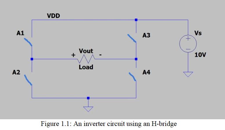
1) In LTSpice. Replace A1 to A4 in the circuit by using transistors shown in Figure 1.1. And how to determine the base or gate driving circuits for the transistors for A1 to A4. Use a resistor of 20Ω as the load. To generate the gate or base driving signals for A1 to A4, use piecewise linear voltage sources. Explain the choice of the components.
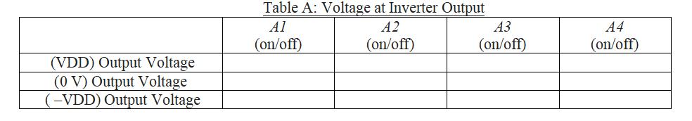
2) How to adjust A1 to A4 switching sequences to get the output voltage. A1 and A2 should not be turned on at the same time. Similarly, A3 and A4 should not be turned on at the same time. Please fill in the Table A below.
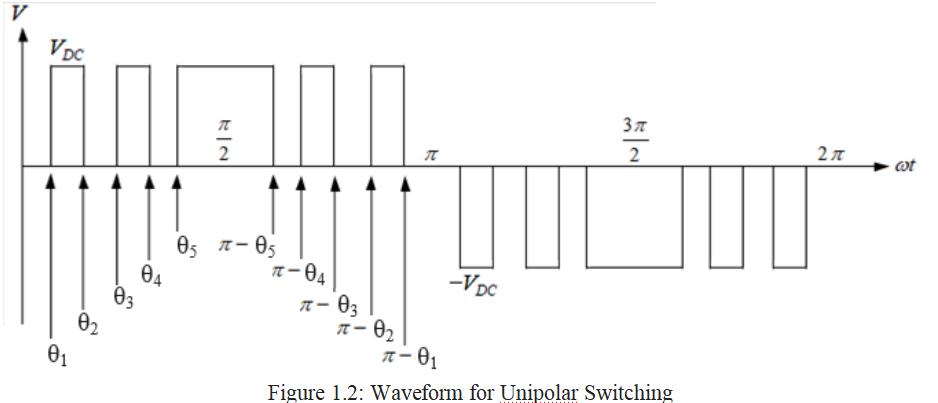
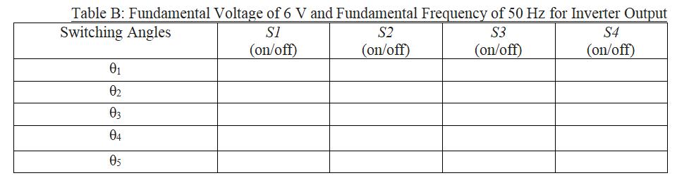
3) Apply the unipolar PWM switching technique as depicted in Figure 1.2 and change the switching patterns of A1 to A4 to produce an output voltage with a fundamental frequency of 50 Hz and a fundamental output voltage of 6 V. Use θ1, θ2 and θ3 switching angles in your settings. Find the modulation index, m. Enter the values in Table B. Give an explanation of your findings.
4) Get the switching angles with the fundamental output voltage ranging from 6 V to 9 V using an incremental of 0.2 V. The fundamental output voltage must be produced by the obtained switching angles, with the third and fifth harmonics either eliminated or at least reduced to 0.25 per cent of the fundamental output voltage. Fill in the Table C below. Compare the outcomes of the FFT results obtained from the simulations and the hand calculations (using the Fourier Series) to describe your findings.
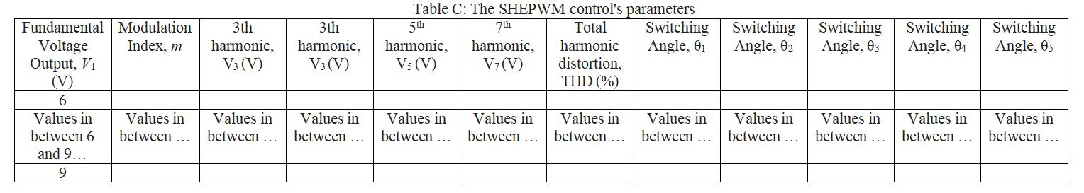 5) Plot a graph illustrating how the modulation index, the corresponding switching angles, the magnitude of the third, fifth, and seventh harmonics, and the THD are all related to one another. The modulation index should be set as the x-axis. Describe your conclusions.
A1 A2 VDD + Vout Load A3 A4 Figure 1.1: An inverter circuit using an H-bridge + Vs 10V
Step by Step Solution
3.47 Rating (154 Votes )
There are 3 Steps involved in it
To accomplish this lab in LTspice youll need to follow several steps Below is a detailed guide addressing each question 1 Replace A1 to A4 with Transi... View full answer

Get step-by-step solutions from verified subject matter experts