

Question: Attached you will find four figures, each showing a beam with different loads and supports. For each beam, draw a full free body diagram. For
Attached you will find four figures, each showing a beam with different loads and supports.
For each beam, draw a full free body diagram. For that, you just draw the beam and you show forces at each point where forces are applied the supports and the load points.
Show the coordinate system and a separate figure to show directions for forces and moments drawing that by itself keeps it out of your way
For the applied loads as shown, show the force and, if the force is applied at an angle, show the x and y components.
For each support show any possible reaction forces x and y components and IF possible, a reaction moment.
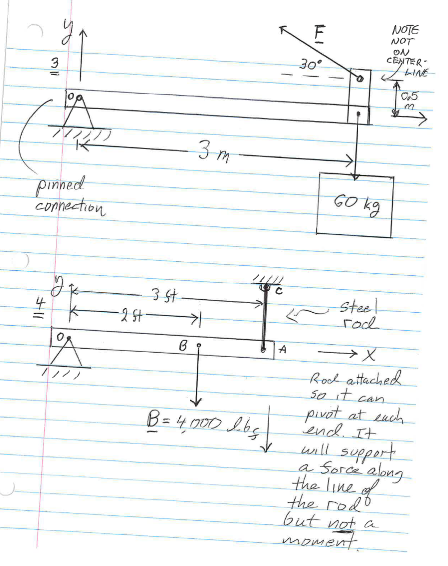
For a pinned connection anchored in place no rollers this can support a reaction force in the x and y directions. It CANNOT support a reaction moment. See left end of fig
For a pinned connection on rollers a roller support this can only support a reaction force at right angles to the rollers. If the rollers run on a horizontal surface, this can only support a reaction force in the vertical direction. That is limited to a reaction force against the rollers. In the figures Ive drawn, that would be a reaction force upwards, meaning that the beam end is being pushed down on the rollers by the other forces. If the other forces would lift the end of the beam, it will be lifted off the rollers. See right end of figure
ENGT Statics and Strength of Materials rd Homework Assignment
For a fixed end cantilever beam this can support reaction forces in both the x and y directions AND a reaction moment. See right end of figure
About moments IF the line of action of the applied force goes through the pivot point point O in my figures it cannot create a moment. IF the line of action does NOT go through the pivot point, it will cause a moment.
For example, Fig force at B that will cause a moment equal to the distance from O to B times the force.
In figure for force E only the y component of the force will cause a moment. The x component acts on a line of action that passes through point O
Think about force F in # The y component will cause a moment. The x component is applied along a line that does NOT pass through the pivot point O Will it create a moment about OHINT: YES
Heres what I want you to do
For each problem, draw the free body diagram. Use the conditions for static equilibrium to find the reaction forces and if possible reaction moment. Youll sum the forces in the x direction, then the forces in the y direction, and, finally, look at moments. Id start by looking at moments about Point O Looking at moments about Point O takes the reaction forces at O out of the picture. In # the sum of the moments will give you the reaction force in the y direction at the roller support at C
In problem I want to introduce something from the strength of materials side. Rod
AC has a diameter of inches. The normal stress due to the load in the rod is given by
FA
where F is the force in the rod and A is the cross section area. Once you find the force in the rod, you can calculate the normal stress.
This is in units of ForceArea pounds per square inch in English units; something related to Pascals in metric units either megaPascals MPa Nm; this is also Nmm
Step by Step Solution
There are 3 Steps involved in it
1 Expert Approved Answer
Step: 1 Unlock

Question Has Been Solved by an Expert!
Get step-by-step solutions from verified subject matter experts
Step: 2 Unlock
Step: 3 Unlock