

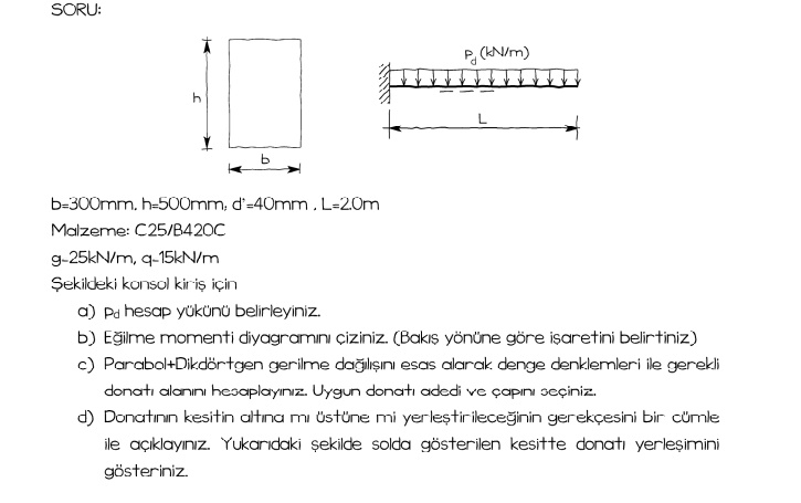
Question: b - 3 0 0 mm , h - 5 0 0 mm , 6 - 4 0 mm . L - 2 0 m
bmmhmmmmLm
Material: CC
gkNm qkNm
For the cantilever beam in the figure
a Determine the pd calculation load
b Draw the bending moment diagram. Indicate the sign according to the viewing direction
c Calculate the required reinforcement area with balance equations based on the parabola rectangular stress distribution. Calculate the appropriate number and diameter of reinforcement.
d Explain in one sentence the reason why the equipment will be placed above or below the section. Show the reinforcement placement in the section shown on the left in the figure above.
Step by Step Solution
There are 3 Steps involved in it
1 Expert Approved Answer
Step: 1 Unlock

Question Has Been Solved by an Expert!
Get step-by-step solutions from verified subject matter experts
Step: 2 Unlock
Step: 3 Unlock