

Question: B 5 ( 3 0 pts , Text 6 . 1 7 , modified ) : For the configuration shown in Figure below, assume plane
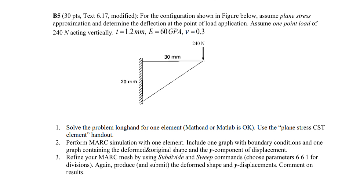
B pts Text modified: For the configuration shown in Figure below, assume plane stress approximation and determine the deflection at the point of load application. Assume one point load of N acting vertically. GPA,
Solve the problem longhand for one element Mathcad or Matlab is OK Use the "plane stress CST element" handout.
Perform MARC simulation with one element. Include one graph with boundary conditions and one graph containing the deformed&original shape and the component of displacement.
Refine your MARC mesh by using Subdivide and Sweep commands choose parameters for divisions Again, produce and submit the deformed shape and displacements. Comment on results.
Step by Step Solution
There are 3 Steps involved in it
1 Expert Approved Answer
Step: 1 Unlock

Question Has Been Solved by an Expert!
Get step-by-step solutions from verified subject matter experts
Step: 2 Unlock
Step: 3 Unlock