

Question: b ) Gravity load path in a building frame: The goal of this exercise is to understand the gravity load path in a steel framing
b Gravity load path in a building frame: The goal of this exercise is to understand the gravity load path
in a steel framing system. We model a frame with a floor slab in LARSA and obtain maximum internal
forces in the joists, girders and columns. We also perform a hand calculation based on tributary areas
and application of equilibrium. We compare the two sets of results to gain an appreciation for how
the load path works, and also of oneway action of the slab.
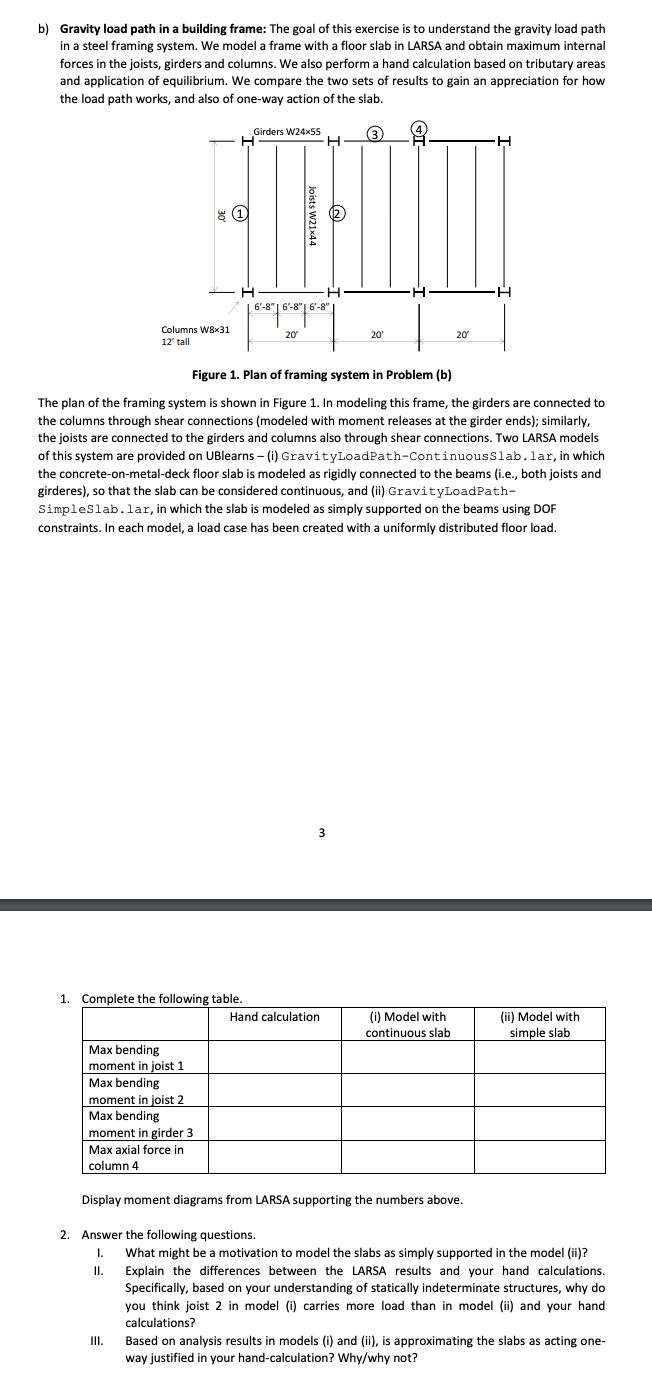
Figure Plan of framing system in Problem b
The plan of the framing system is shown in Figure In modeling this frame, the girders are connected to
the columns through shear connections modeled with moment releases at the girder ends; similarly,
the joists are connected to the girders and columns also through shear connections. Two LARSA models
of this system are provided on UBlearns i GravityLoadPathContinuousSlab. lar, in which
the concreteonmetaldeck floor slab is modeled as rigidly connected to the beams ie both joists and
girderes so that the slab can be considered continuous, and ii GravityLoadPath
SimpleSlab. lar, in which the slab is modeled as simply supported on the beams using DOF
constraints. In each model, a load case has been created with a uniformly distributed floor load.
Complete the following table.
Display moment diagrams from LARSA supporting the numbers above.
Answer the following questions.
I. What might be a motivation to model the slabs as simply supported in the model ii
II Explain the differences between the LARSA results and your hand calculations.
Specifically, based on your understanding of statically indeterminate structures, why do
you think joist in model i carries more load than in model ii and your hand
calculations?
III. Based on analysis results in models i and ii is approximating the slabs as acting one
way justified in your handcalculation? Whywhy not? c Lateral load path in a building frame:
I. What members would you add to the framing in Figure to provide a reasonable load
path for lateral loads.
II Describe the resulting lateral load path.
Step by Step Solution
There are 3 Steps involved in it
1 Expert Approved Answer
Step: 1 Unlock

Question Has Been Solved by an Expert!
Get step-by-step solutions from verified subject matter experts
Step: 2 Unlock
Step: 3 Unlock