

Question: b . The beam shown in FIGURE Q 2 b is simply supported with a pin and roller at both ends, and is subjected to
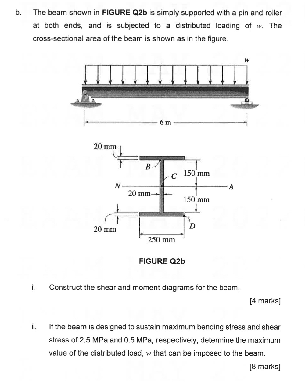
b The beam shown in FIGURE Qb is simply supported with a pin and roller at both ends, and is subjected to a distributed loading of The crosssectional area of the beam is shown as in the figure.
FIGURE Qb
i Construct the shear and moment diagrams for the beam.
marks
ii If the beam is designed to sustain maximum bending stress and shear stress of MPa and MPa respectively, determine the maximum value of the distributed load, that can be imposed to the beam.
marks
Step by Step Solution
There are 3 Steps involved in it
1 Expert Approved Answer
Step: 1 Unlock

Question Has Been Solved by an Expert!
Get step-by-step solutions from verified subject matter experts
Step: 2 Unlock
Step: 3 Unlock