

Question: Back to the ray tracing simulation, for a diverging lens. Physlet Physics by Christian and Belloni: Exploration 35.2 (compadre.org) Open the simulation. Diverging Lens Ray
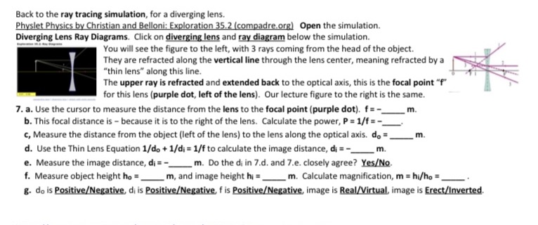
Back to the ray tracing simulation, for a diverging lens. Physlet Physics by Christian and Belloni: Exploration 35.2 (compadre.org) Open the simulation. Diverging Lens Ray Diagrams. Click on diverging lens and ray diagram below the simulation. You will see the figure to the left, with 3 rays coming from the head of the object. They are refracted along the vertical line through the lens center, meaning refracted by a "thin lens" along this line. The upper ray is refracted and extended back to the optical axis, this is the focal point "f" for this lens (purple dot, left of the lens). Our lecture figure to the right is the same. 7. a. Use the cursor to measure the distance from the lens to the focal point (purple dot). f = - m. b. This focal distance is - because it is to the right of the lens. Calculate the power, P = 1/f =- c, Measure the distance from the object (left of the lens) to the lens along the optical axis. do = m. d. Use the Thin Lens Equation 1/do + 1/dj = 1/f to calculate the image distance, di = =_ m. e. Measure the image distance, di = - m. Do the di in 7.d. and 7.e. closely agree? Yes/No. f. Measure object height ho =_ m, and image height hi =_m. Calculate magnification, m = hi/ho = g. do is Positive/Negative, di is Positive/Negative, f is Positive/Negative, image is Real/Virtual, image is Erect/Inverted
Step by Step Solution
There are 3 Steps involved in it

Get step-by-step solutions from verified subject matter experts