

Question: Background: In this exercise, a feedback controlled system, utilizing a simplified model of a DC motor [with some mechanical load] is used to explore some
![model of a DC motor [with some mechanical load] is used to](https://dsd5zvtm8ll6.cloudfront.net/si.experts.images/questions/2024/09/66f316057bb91_91766f31605296f5.jpg)
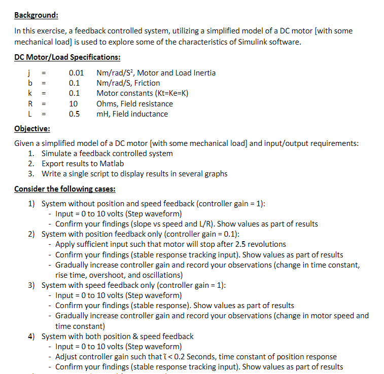
Background: In this exercise, a feedback controlled system, utilizing a simplified model of a DC motor [with some mechanical load] is used to explore some of the characteristics of Simulink software DC Motor/Load Specifications: 0.01 0.1 0.1 10 0.5 Nm/rad/S, Motor and Load Inertia Nm/rad/S, Friction Motor constants (Kt-Ke-K) Ohms, Field resistance mH, Field inductance = Objective Given a simplified model of a DC motor [with some mechanical load] and input/output requirements 1. Simulate a feedback controlled system 2. Export results to Matlab 3. Write a single script to display results in several graphs Consider the following cases: 1) System without position and speed feedback (controller gain - 1) Input 0 to 10 volts (Step waveform) - Confirm your findings (slope vs speed and L/R). Show values as part of results 2) System with position feedback only (controller gain=0.1) Apply sufficient input such that motor will stop after 2.5 revolutions - Confirm your findings (stable response tracking input). Show values as part of results - Gradually increase controller gain and record your observations (change in time constant, rise time, overshoot, and oscillations) 3) System with speed feedback only (controller gain -1): -Input = 0 to 10 volts (Step waveform) - Confirm your findings (stable response). Show values as part of results - Gradually increase controller gain and record your observations (change in motor speed and time constant) 4) System with both position & speed feedback -Input = 0 to 10 volts (Step waveform) Adjust controller gain such that T
Step by Step Solution
There are 3 Steps involved in it

Get step-by-step solutions from verified subject matter experts