

Question: based on system identified please do Hazop ? or Bow - Tie methord to identify HAZARD 2.1 Sub-system #1: LH2 storage The effective storage of
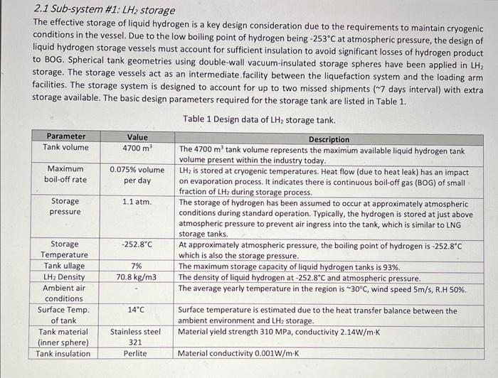
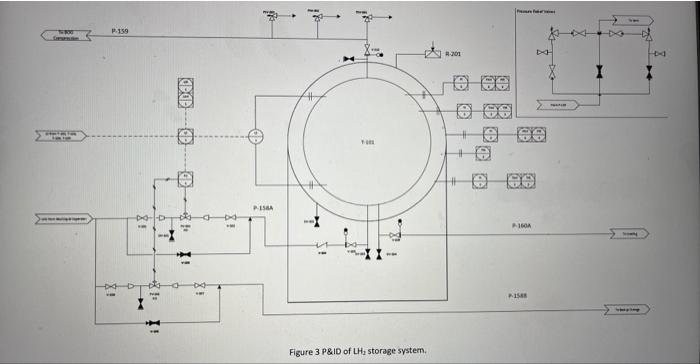
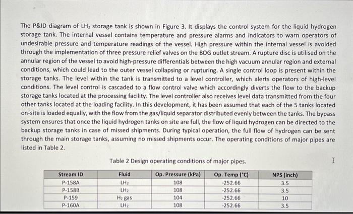
2.1 Sub-system \#1: LH2 storage The effective storage of liquid hydrogen is a key design consideration due to the requirements to maintain cryogenic conditions in the vessel. Due to the low boiling point of hydrogen being 253C at atmospheric pressure, the design of liquid hydrogen storage vessels must account for sufficient insulation to avoid significant losses of hydrogen product to BOG. Spherical tank geometries using double-wall vacuum-insulated storage spheres have been applied in LH2 storage. The storage vessels act as an intermediate facility between the liquefaction system and the loading arm facilities. The storage system is designed to account for up to two missed shipments ( 7 days interval) with extra storage available. The basic design parameters required for the storage tank are listed in Table 1. Figure 3 PgiD of LH2 storage system. The P\&ID diagram of LH2 storage tank is shown in Figure 3. It displays the control system for the liquid hydrogen storage tank. The internal vessel contains temperature and pressure alarms and indicators to warn operators of undesirable pressure and temperature readings of the vessel. High pressure within the internal vessel is avoided through the implementation of three pressure relief valves on the BOG outlet stream. A rupture disc is utilised on the annular region of the vessel to avoid high-pressure differentials between the high vacuum annular region and external conditions, which could lead to the outer vessel collapsing or rupturing. A single control loop is present within the storage tanks. The level within the tank is transmitted to a level controller, which alerts operators of high-level conditions. The level control is cascaded to a flow control valve which accordingly diverts the flow to the backup storage tanks located at the processing facility. The level controller also receives level data transmitted from the four other tanks located at the loading facility. In this development, it has been assumed that each of the 5 tanks located on-site is loaded equally, with the flow from the gas/liquid separator distributed evenly between the tanks. The bypass system ensures that once the liquid hydrogen tanks on site are full, the flow of liquid hydrogen can be directed to the backup storage tanks in case of missed shipments. During typical operation, the full flow of hydrogen can be sent through the main storage tanks, assuming no missed shipments occur. The operating conditions of major pipes are listed in Table 2. Table 2 Design operating conditions of major pipes. 2.1 Sub-system \#1: LH2 storage The effective storage of liquid hydrogen is a key design consideration due to the requirements to maintain cryogenic conditions in the vessel. Due to the low boiling point of hydrogen being 253C at atmospheric pressure, the design of liquid hydrogen storage vessels must account for sufficient insulation to avoid significant losses of hydrogen product to BOG. Spherical tank geometries using double-wall vacuum-insulated storage spheres have been applied in LH2 storage. The storage vessels act as an intermediate facility between the liquefaction system and the loading arm facilities. The storage system is designed to account for up to two missed shipments ( 7 days interval) with extra storage available. The basic design parameters required for the storage tank are listed in Table 1. Figure 3 PgiD of LH2 storage system. The P\&ID diagram of LH2 storage tank is shown in Figure 3. It displays the control system for the liquid hydrogen storage tank. The internal vessel contains temperature and pressure alarms and indicators to warn operators of undesirable pressure and temperature readings of the vessel. High pressure within the internal vessel is avoided through the implementation of three pressure relief valves on the BOG outlet stream. A rupture disc is utilised on the annular region of the vessel to avoid high-pressure differentials between the high vacuum annular region and external conditions, which could lead to the outer vessel collapsing or rupturing. A single control loop is present within the storage tanks. The level within the tank is transmitted to a level controller, which alerts operators of high-level conditions. The level control is cascaded to a flow control valve which accordingly diverts the flow to the backup storage tanks located at the processing facility. The level controller also receives level data transmitted from the four other tanks located at the loading facility. In this development, it has been assumed that each of the 5 tanks located on-site is loaded equally, with the flow from the gas/liquid separator distributed evenly between the tanks. The bypass system ensures that once the liquid hydrogen tanks on site are full, the flow of liquid hydrogen can be directed to the backup storage tanks in case of missed shipments. During typical operation, the full flow of hydrogen can be sent through the main storage tanks, assuming no missed shipments occur. The operating conditions of major pipes are listed in Table 2. Table 2 Design operating conditions of major pipes
Step by Step Solution
There are 3 Steps involved in it

Get step-by-step solutions from verified subject matter experts