

Question: Book: Programmable Logic Controllers: emphasis on design and application, 3rd edition. Author: Kelvin T. Erickson problem: 2-24 problem is taken from ar P2-24. Implement the
Book: Programmable Logic Controllers: emphasis on design and application, 3rd edition.
Author: Kelvin T. Erickson
problem: 2-24
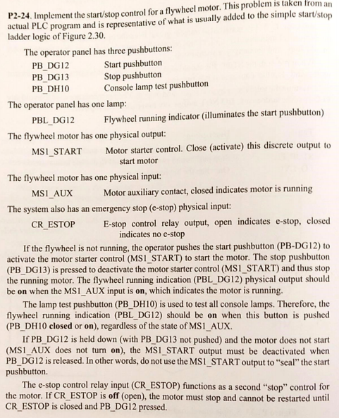
problem is taken from ar P2-24. Implement the start/stop control for a flywheel motor. This ctual PLC program and is representative of what is usually added to the simple start/stop ladder logic of Figure 2.30 The operator panel has three pushbuttons PB DG12 PB DG13 PB DHI0 Start pushbutton Stop pushbutton Console lamp test pushbutton The operator panel has one lamp PBL DG12 Flywheel running indicator (illuminates the start pushbutton) The flywheel motor has one physical output: ART Motor starter control. Close (activate) this discrete outputo start motor The flywheel motor has one physical input MS1 AUX Motor auxiliary contact, closed indicates motor is running The system also has an emergency stop (e-stop) physical input CR ESTOP E-stop control relay output, open indicates e-stop, closed indicates no e-stop If the flywheel is not running, the operator pushes the start pushbutton (PB-DG12) to activate the motor starter control (MSI START) to start the motor. The stop pushbutton (PB_DG13) is pressed to deactivate the motor starter control (MS1_START) and thus stop the running motor. The flywheel running indication (PBL_DG12) physical output should be on when the MS1 AUX input is on, which indicates the motor is running The lamp test pushbutton (PB_DH10) is used to test all console lamps. Therefore, the flywheel running indication (PBL_DG12) should be on when this button is pushed (PB_DHI0 closed or on), regardless of the state of MS1 AUX. If PB_DG12 is held down (with PB_DG13 not pushed) and the motor does not start (MS1 AUX does not turn on), the MSI_START output must be deactivated whern PB_DG12 is released. In other words, do not use the MS1_START output to "seal" the start pushbutton. The e-stop control relay input (CR ESTOP) functions as a second "stop" control for the motor. If CR ESTOP is off (open), the motor must stop and cannot be restarted until CR ESTOP is closed and PB DG12 pressed problem is taken from ar P2-24. Implement the start/stop control for a flywheel motor. This ctual PLC program and is representative of what is usually added to the simple start/stop ladder logic of Figure 2.30 The operator panel has three pushbuttons PB DG12 PB DG13 PB DHI0 Start pushbutton Stop pushbutton Console lamp test pushbutton The operator panel has one lamp PBL DG12 Flywheel running indicator (illuminates the start pushbutton) The flywheel motor has one physical output: ART Motor starter control. Close (activate) this discrete outputo start motor The flywheel motor has one physical input MS1 AUX Motor auxiliary contact, closed indicates motor is running The system also has an emergency stop (e-stop) physical input CR ESTOP E-stop control relay output, open indicates e-stop, closed indicates no e-stop If the flywheel is not running, the operator pushes the start pushbutton (PB-DG12) to activate the motor starter control (MSI START) to start the motor. The stop pushbutton (PB_DG13) is pressed to deactivate the motor starter control (MS1_START) and thus stop the running motor. The flywheel running indication (PBL_DG12) physical output should be on when the MS1 AUX input is on, which indicates the motor is running The lamp test pushbutton (PB_DH10) is used to test all console lamps. Therefore, the flywheel running indication (PBL_DG12) should be on when this button is pushed (PB_DHI0 closed or on), regardless of the state of MS1 AUX. If PB_DG12 is held down (with PB_DG13 not pushed) and the motor does not start (MS1 AUX does not turn on), the MSI_START output must be deactivated whern PB_DG12 is released. In other words, do not use the MS1_START output to "seal" the start pushbutton. The e-stop control relay input (CR ESTOP) functions as a second "stop" control for the motor. If CR ESTOP is off (open), the motor must stop and cannot be restarted until CR ESTOP is closed and PB DG12 pressed
Step by Step Solution
There are 3 Steps involved in it

Get step-by-step solutions from verified subject matter experts