

Question: Build a digital circuit which controls an automatic garage door opener. The garage door circuit has three bits of input. The first input, called button,
Build a digital circuit which controls an automatic garage door opener. The garage door circuit has
three bits of input. The first input, called button, comes from a the main control button used to open
or close the garage door. When pressed button otherwise button The garage door rides
in a track, at the top and bottom of of which are two limit switches. The top limit switch equals
when the garage door is all the way up otherwise its output equals The bottom limit switch equals
when the garage door is all the way down, otherwise its output equals The garage door circuit
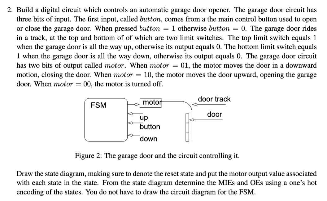
has two bits of output called motor. When motor the motor moves the door in a downward
motion, closing the door. When motor the motor moves the door upward, opening the garage
door. When motor the motor is turned off.
Figure : The garage door and the circuit controlling it
Draw the state diagram, making sure to denote the reset state and put the motor output value associated
with each state in the state. From the state diagram determine the MIEs and OEs using a one's hot
encoding of the states. You do not have to draw the circuit diagram for the FSM
Step by Step Solution
There are 3 Steps involved in it
1 Expert Approved Answer
Step: 1 Unlock

Question Has Been Solved by an Expert!
Get step-by-step solutions from verified subject matter experts
Step: 2 Unlock
Step: 3 Unlock