

Question: By hand, Figure 1 shows a typical visual servoing configuration for industrial robots. It is known as eye-in-hand configuration that a camera is mounted at
By hand,
Figure 1 shows a typical visual servoing configuration for industrial robots. It is known as eye-in-hand configuration that a camera is mounted at the end-effector of the robot. It is a usual practice to use a checker board for camera calibration.
This coursework is a simplified case of this problem. Instead of a checker board, we use a fiducial pattern in this case. The relative pose between the workbench and the camera needs to b e calibrated first using the fiducial pattern at a known position. 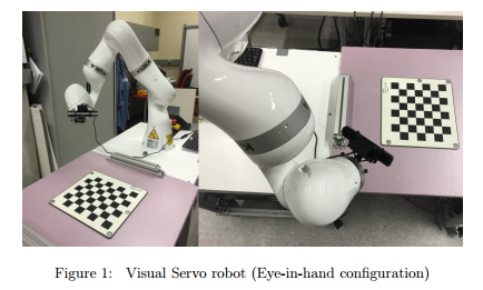
In this coursework, we assume the initial position for the robot camera is the origin (0 , 0 , 0). The positive z-axis is the cameras optical axis which intersects with the workbench surface at position D (as depicted in figure 3). The focal length of the camera is 7mm. The workbench surface is parallel to the xy-plane and perpendicular to the z-axis. The distance from the surface to the camera is 500 mm
Task:
By hand, work out the expected coordinates of the vertices (A, B, C, D, E, F, G) projected on the image-plane coordinate space. Tip: First construct the camera matrix and the coordinates of the corresponding vertices in the 3D space with respect to the camera frame.
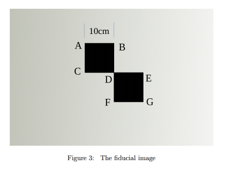
Figure 1: Visual Servo robot (Eye-in-hand configuration) 10cm Figure 3: The fiducial image Figure 1: Visual Servo robot (Eye-in-hand configuration) 10cm Figure 3: The fiducial image
Step by Step Solution
There are 3 Steps involved in it

Get step-by-step solutions from verified subject matter experts