

Question: C.9) (Based on problem B.31 in Appendix B.) Assuming that the delay of a full and half-adders is 27, calculate the delay of both the
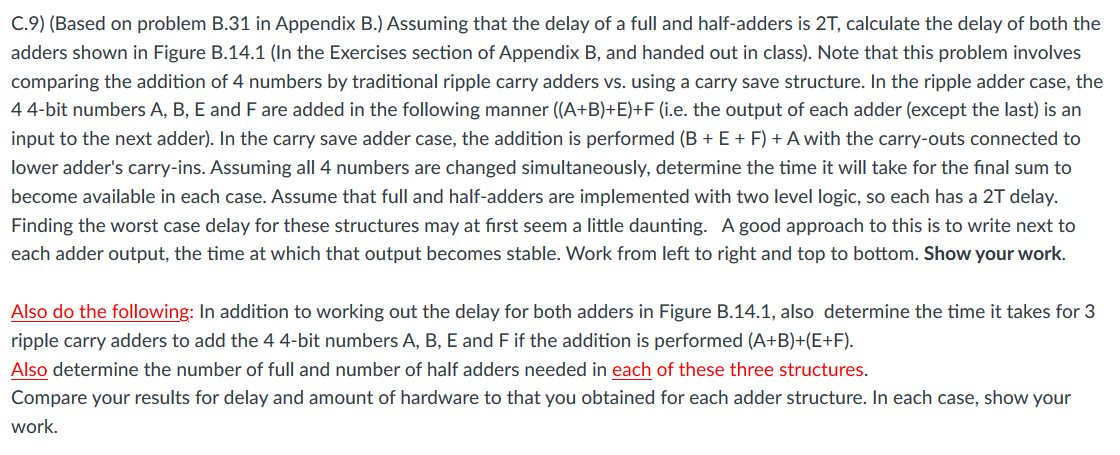
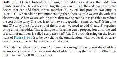
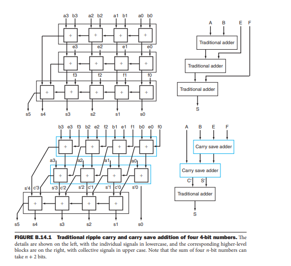
C.9) (Based on problem B.31 in Appendix B.) Assuming that the delay of a full and half-adders is 27, calculate the delay of both the adders shown in Figure B.14.1 (In the Exercises section of Appendix B, and handed out in class). Note that this problem involves comparing the addition of 4 numbers by traditional ripple carry adders vs. using a carry save structure. In the ripple adder case, the 44-bit numbers A, B, E and F are added in the following manner (A+B)+E)+F (i.e. the output of each adder (except the last) is an input to the next adder). In the carry save adder case, the addition is performed (B + E + F) + A with the carry-outs connected to lower adder's carry-ins. Assuming all 4 numbers are changed simultaneously, determine the time it will take for the final sum to become available in each case. Assume that full and half-adders are implemented with two level logic, so each has a 27 delay. Finding the worst case delay for these structures may at first seem a little daunting. A good approach to this is to write next to each adder output, the time at which that output becomes stable. Work from left to right and top to bottom. Show your work. Also do the following: In addition to working out the delay for both adders in Figure B.14.1, also determine the time it takes for 3 ripple carry adders to add the 4 4-bit numbers A, B, E and F if the addition is performed (A+B)+(E+F). Also determine the number of full and number of half adders needed in each of these three structures. Compare your results for delay and amount of hardware to that you obtained for each adder structure. In each case, show your work. B.31 [10] Instead of thinking of an adder as a device that adds two numbers and then links the carries together, we can think of the adder as a hardware device that can add three inputs together (ai, bi, ci) and produce two outputs (s, ci + 1). When adding two numbers together, there is little we can do with this observation. When we are adding more than two operands, it is possible to reduce the cost of the carry. The idea is to form two independent sums, called S' (sum bits) and C' (carry bits). At the end of the process, we need to add C and S' together using a normal adder. This technique of delaying carry propagation until the end of a sum of numbers is called carry save addition. The block drawing on the lower right of Figure B.14.1 (see below) shows the organization, with two levels of carry save adders connected by a single normal adder. Calculate the delays to add four 16-bit numbers using full carry-lookahead adders versus carry save with a carry-lookahead adder forming the final sum. (The time unit T in Exercise B.28 is the same.) a3 b3 a2 b2 al b1 al bo A 00 E F + Traditional adder e3 e2 e1 e0 + Traditional adder f3 f2 f1 fo Traditional adder + S 55 54 S3 s1 50 b3e3 13 b2 e2 t2 bi et ft bo e fo B E F + + Carry save adder a3 /a2, Carry save adder CO Traditional adder s'4c3 s'3c2 s2 d'1 s'1 co s'o + + + s s5 54 s3 52 s1 SO FIGURE B.14.1 Traditional ripple carry and carry save addition of four 4-bit numbers. The details are shown on the left, with the individual signals in lowercase, and the corresponding higher-level blocks are on the right with collective signals in upper case. Note that the sum of four n-bit numbers can take n +2 bits. C.9) (Based on problem B.31 in Appendix B.) Assuming that the delay of a full and half-adders is 27, calculate the delay of both the adders shown in Figure B.14.1 (In the Exercises section of Appendix B, and handed out in class). Note that this problem involves comparing the addition of 4 numbers by traditional ripple carry adders vs. using a carry save structure. In the ripple adder case, the 44-bit numbers A, B, E and F are added in the following manner (A+B)+E)+F (i.e. the output of each adder (except the last) is an input to the next adder). In the carry save adder case, the addition is performed (B + E + F) + A with the carry-outs connected to lower adder's carry-ins. Assuming all 4 numbers are changed simultaneously, determine the time it will take for the final sum to become available in each case. Assume that full and half-adders are implemented with two level logic, so each has a 27 delay. Finding the worst case delay for these structures may at first seem a little daunting. A good approach to this is to write next to each adder output, the time at which that output becomes stable. Work from left to right and top to bottom. Show your work. Also do the following: In addition to working out the delay for both adders in Figure B.14.1, also determine the time it takes for 3 ripple carry adders to add the 4 4-bit numbers A, B, E and F if the addition is performed (A+B)+(E+F). Also determine the number of full and number of half adders needed in each of these three structures. Compare your results for delay and amount of hardware to that you obtained for each adder structure. In each case, show your work. B.31 [10] Instead of thinking of an adder as a device that adds two numbers and then links the carries together, we can think of the adder as a hardware device that can add three inputs together (ai, bi, ci) and produce two outputs (s, ci + 1). When adding two numbers together, there is little we can do with this observation. When we are adding more than two operands, it is possible to reduce the cost of the carry. The idea is to form two independent sums, called S' (sum bits) and C' (carry bits). At the end of the process, we need to add C and S' together using a normal adder. This technique of delaying carry propagation until the end of a sum of numbers is called carry save addition. The block drawing on the lower right of Figure B.14.1 (see below) shows the organization, with two levels of carry save adders connected by a single normal adder. Calculate the delays to add four 16-bit numbers using full carry-lookahead adders versus carry save with a carry-lookahead adder forming the final sum. (The time unit T in Exercise B.28 is the same.) a3 b3 a2 b2 al b1 al bo A 00 E F + Traditional adder e3 e2 e1 e0 + Traditional adder f3 f2 f1 fo Traditional adder + S 55 54 S3 s1 50 b3e3 13 b2 e2 t2 bi et ft bo e fo B E F + + Carry save adder a3 /a2, Carry save adder CO Traditional adder s'4c3 s'3c2 s2 d'1 s'1 co s'o + + + s s5 54 s3 52 s1 SO FIGURE B.14.1 Traditional ripple carry and carry save addition of four 4-bit numbers. The details are shown on the left, with the individual signals in lowercase, and the corresponding higher-level blocks are on the right with collective signals in upper case. Note that the sum of four n-bit numbers can take n +2 bits
Step by Step Solution
There are 3 Steps involved in it

Get step-by-step solutions from verified subject matter experts