

Question: can anyone do that please ? EL-100 LAB #2 CHOD Measuring DC Current, Voltage, and Resistance OBJECTIVE: To become proficient in the construction of simple
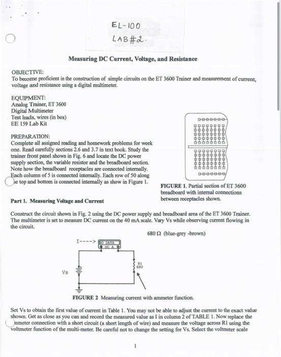
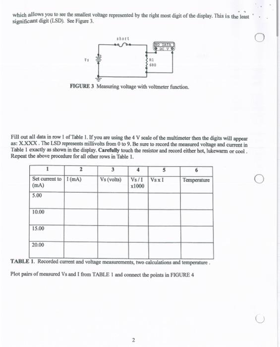
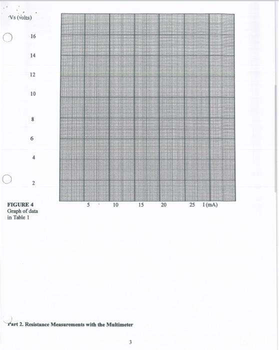
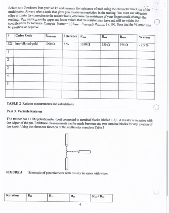
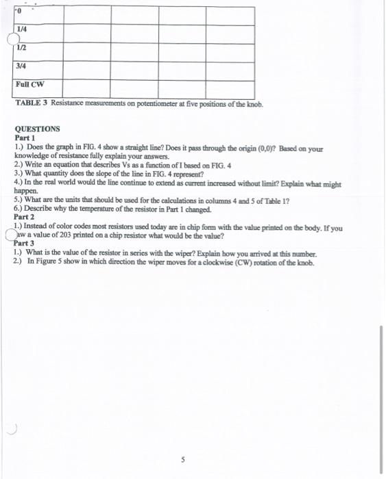
EL-100 LAB #2 CHOD Measuring DC Current, Voltage, and Resistance OBJECTIVE: To become proficient in the construction of simple circuits on the ET 3600 Trainer and measurement of current, voltage and resistance using a digital multimeter. EQUIPMENT: Analog Tminer, ET 3600 Digital Multimeter Test leads, wires (in box) EE 159 Lab Kit PREPARATION: Complete all assigned reading and homework problems for week one. Read carefully sections 2.6 and 3.7 in text book. Study the trainer front panel shown in Fig. 6 and locate the DC power supply section, the variable resistor and the breadboard section. Note how the breadboard receptacles are connected internally. Each column of 5 is connected internally. Each row of 50 along Je top and bottom is connected internally as show in Figure 1. FIGURE 1. Partial section of ET 3600 breadboard with internal connections Part 1. Measuring Voltage and Current between receptacles shown Construct the circuit shown in Fig. 2 using the DC power supply and breadboard area of the ET 3600 Trainer. The multimeter is set to measure DC current on the 40 mA scale. Vary Vs while observing current flowing in the circuit 6800 (blue-grey-brown) I----> 0-0-0-000 Vs FIGURE 2 Measuring current with ammeter function. Set Vs to obtain the first value of current in Table 1. You may not be able to adjust the current to the exact value shown. Get as close as you can and record the measured value as I in column 2 of TABLE 1. Now replace the nameter connection with a short circuit (a short length of wire) and measure the voltage across Rl using the voltmeter function of the multi-meter. Be careful not to change the setting for Vs. Select the voltmeter scale which allows you to see the smallest voltage represented by the right most digit of the display. This is the least significant digit (LSD). See Figure 3. short NORAMA OCYK RI 680 FIGURE 3 Measuring voltage with voltmeter function. Fill out all data in row I of Table 1. If you are using the 4 V scale of the multimeter then the digits will appear as: X.XXX. The LSD represents millivolts from 0 to 9. Be sure to record the measured voltage and current in Table 1 exactly as shown in the display. Carefully touch the resistor and record either bot, lukewarm or cool Repeat the above procedure for all other rows in Table 1. 3 5 Set current to (mA) Vs (volts) Vs/l. VsxI Temperature (mA) x1000 5.00 2 10.00 15.00 20.00 TABLE 1. Recorded current and voltage measurements, two calculations and temperature Plot pairs of measured Vs and I from TABLE 1 and connect the points in FIGURE 4 Vs (volts) 16 14 12 10 6 5 10 15 20 25 1(mA) FIGURE 4 Graph of data in Table 1 Part 2. Resistance Measurements with the Multimeter Select any 5 resistors from your lab kit and measure the resistance of each using the ohmmeter function of the multimeter. Always select a scale that gives you maximum resolution in the reading. You must use alligator clips to make the connection to the resistor leads, otherwise the resistance of your fingers could change the reading. R. and Rure the upper and lower values that the resistor may have and still be within the specification for tolerance. Compute %error = {(R-Retrede Ruders } x 100. Note that the % error may be positive or negative Color Code Re Tolerance R R R % error EX brn-bik-red-gold 10000 5% 1050 9502 975 - 2.5% 1 2 3 4 5 TABLE 2 Resistor measurements and calculations Part 3. Variable Resistors The trainer has a 1 ks potentiometer (pot) connected to terminal blocks labeled 1,2,3. A resistor is in series with the wiper of the pot. Resistance measurements can be made between any two terminal blocks for any rotation of the knob. Using the ohmmeter function of the multimeter complete Table 3 FIGURE 5 Schematic of potentiometer with resistor in series with wiper Rotation Rua R. Rus Ra+R 4 PO 1/4 1/2 3/4 Full CW TABLE 3 Resistance measurements on potentiometer at five positions of the knob. QUESTIONS Part 1 1.) Does the graph in FIG. 4 show a straight line? Does it pass through the origin (0,0)? Based on your knowledge of resistance fully explain your answers. 2.) Write an equation that describes Vs as a function of I based on FIG. 4 3.) What quantity does the slope of the line in FIG. 4 represent? 4.) In the real world would the line continue to extend as current increased without limit? Explain what might 5.) What are the units that should be used for the calculations in columns 4 and 5 of Table 1? 6.) Describe why the temperature of the resistor in Part I changed. Part 2 1.) Instead of color codes most resistors used today are in chip form with the value printed on the body. If you aw a value of 203 printed on a chip resistor what would be the value? Part 3 1.) What is the value of the resistor in series with the wiper? Explain how you arrived at this number. 2.) In Figure 5 show in which direction the wiper moves for a clockwise (CW) rotation of the knob. 5 EL-100 LAB #2 CHOD Measuring DC Current, Voltage, and Resistance OBJECTIVE: To become proficient in the construction of simple circuits on the ET 3600 Trainer and measurement of current, voltage and resistance using a digital multimeter. EQUIPMENT: Analog Tminer, ET 3600 Digital Multimeter Test leads, wires (in box) EE 159 Lab Kit PREPARATION: Complete all assigned reading and homework problems for week one. Read carefully sections 2.6 and 3.7 in text book. Study the trainer front panel shown in Fig. 6 and locate the DC power supply section, the variable resistor and the breadboard section. Note how the breadboard receptacles are connected internally. Each column of 5 is connected internally. Each row of 50 along Je top and bottom is connected internally as show in Figure 1. FIGURE 1. Partial section of ET 3600 breadboard with internal connections Part 1. Measuring Voltage and Current between receptacles shown Construct the circuit shown in Fig. 2 using the DC power supply and breadboard area of the ET 3600 Trainer. The multimeter is set to measure DC current on the 40 mA scale. Vary Vs while observing current flowing in the circuit 6800 (blue-grey-brown) I----> 0-0-0-000 Vs FIGURE 2 Measuring current with ammeter function. Set Vs to obtain the first value of current in Table 1. You may not be able to adjust the current to the exact value shown. Get as close as you can and record the measured value as I in column 2 of TABLE 1. Now replace the nameter connection with a short circuit (a short length of wire) and measure the voltage across Rl using the voltmeter function of the multi-meter. Be careful not to change the setting for Vs. Select the voltmeter scale which allows you to see the smallest voltage represented by the right most digit of the display. This is the least significant digit (LSD). See Figure 3. short NORAMA OCYK RI 680 FIGURE 3 Measuring voltage with voltmeter function. Fill out all data in row I of Table 1. If you are using the 4 V scale of the multimeter then the digits will appear as: X.XXX. The LSD represents millivolts from 0 to 9. Be sure to record the measured voltage and current in Table 1 exactly as shown in the display. Carefully touch the resistor and record either bot, lukewarm or cool Repeat the above procedure for all other rows in Table 1. 3 5 Set current to (mA) Vs (volts) Vs/l. VsxI Temperature (mA) x1000 5.00 2 10.00 15.00 20.00 TABLE 1. Recorded current and voltage measurements, two calculations and temperature Plot pairs of measured Vs and I from TABLE 1 and connect the points in FIGURE 4 Vs (volts) 16 14 12 10 6 5 10 15 20 25 1(mA) FIGURE 4 Graph of data in Table 1 Part 2. Resistance Measurements with the Multimeter Select any 5 resistors from your lab kit and measure the resistance of each using the ohmmeter function of the multimeter. Always select a scale that gives you maximum resolution in the reading. You must use alligator clips to make the connection to the resistor leads, otherwise the resistance of your fingers could change the reading. R. and Rure the upper and lower values that the resistor may have and still be within the specification for tolerance. Compute %error = {(R-Retrede Ruders } x 100. Note that the % error may be positive or negative Color Code Re Tolerance R R R % error EX brn-bik-red-gold 10000 5% 1050 9502 975 - 2.5% 1 2 3 4 5 TABLE 2 Resistor measurements and calculations Part 3. Variable Resistors The trainer has a 1 ks potentiometer (pot) connected to terminal blocks labeled 1,2,3. A resistor is in series with the wiper of the pot. Resistance measurements can be made between any two terminal blocks for any rotation of the knob. Using the ohmmeter function of the multimeter complete Table 3 FIGURE 5 Schematic of potentiometer with resistor in series with wiper Rotation Rua R. Rus Ra+R 4 PO 1/4 1/2 3/4 Full CW TABLE 3 Resistance measurements on potentiometer at five positions of the knob. QUESTIONS Part 1 1.) Does the graph in FIG. 4 show a straight line? Does it pass through the origin (0,0)? Based on your knowledge of resistance fully explain your answers. 2.) Write an equation that describes Vs as a function of I based on FIG. 4 3.) What quantity does the slope of the line in FIG. 4 represent? 4.) In the real world would the line continue to extend as current increased without limit? Explain what might 5.) What are the units that should be used for the calculations in columns 4 and 5 of Table 1? 6.) Describe why the temperature of the resistor in Part I changed. Part 2 1.) Instead of color codes most resistors used today are in chip form with the value printed on the body. If you aw a value of 203 printed on a chip resistor what would be the value? Part 3 1.) What is the value of the resistor in series with the wiper? Explain how you arrived at this number. 2.) In Figure 5 show in which direction the wiper moves for a clockwise (CW) rotation of the knob. 5
Step by Step Solution
There are 3 Steps involved in it

Get step-by-step solutions from verified subject matter experts