

Question: can someone anyone please help me ?! i am so overwhelmed and lost! please! from the packet tracer to the visio diagram. The ip address
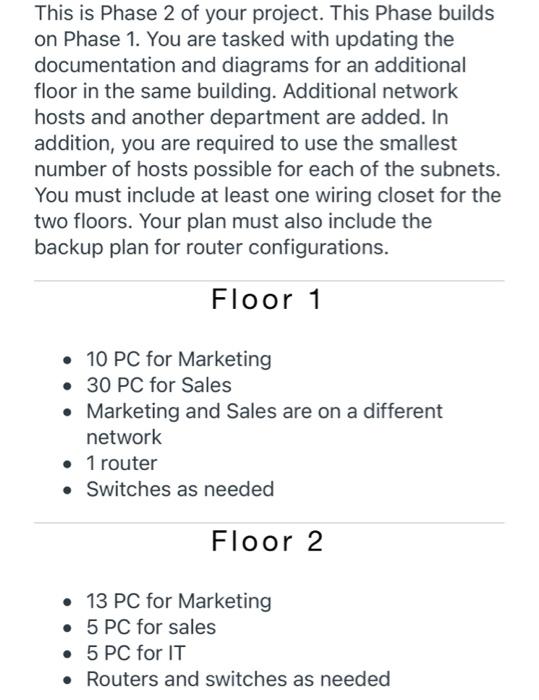
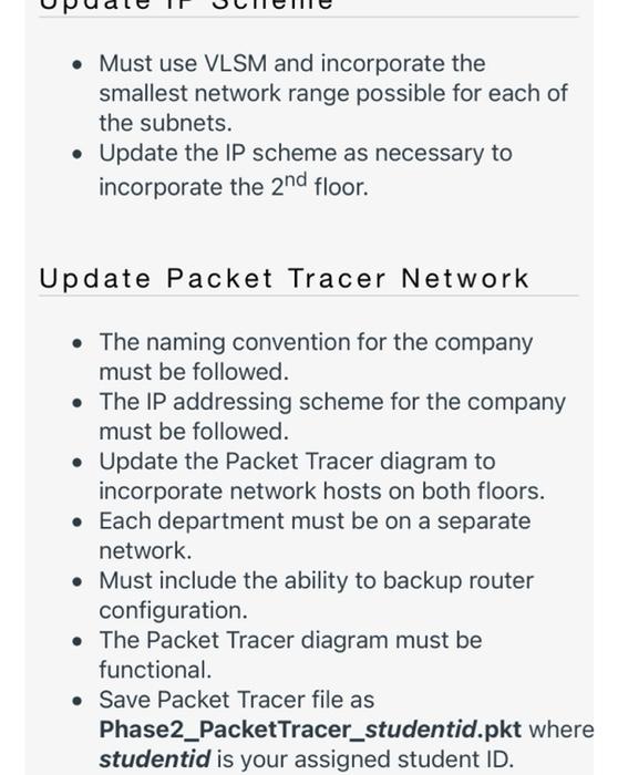
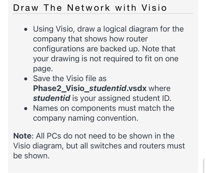
This is Phase 2 of your project. This Phase builds on Phase 1. You are tasked with updating the documentation and diagrams for an additional floor in the same building. Additional network hosts and another department are added. In addition, you are required to use the smallest number of hosts possible for each of the subnets. You must include at least one wiring closet for the two floors. Your plan must also include the backup plan for router configurations. Floor 1 10 PC for Marketing 30 PC for Sales Marketing and Sales are on a different network 1 router Switches as needed Floor 2 13 PC for Marketing 5 PC for sales 5 PC for IT Routers and switches as needed Must use VLSM and incorporate the smallest network range possible for each of the subnets. Update the IP scheme as necessary to incorporate the 2nd floor. Update Packet Tracer Network The naming convention for the company must be followed. The IP addressing scheme for the company must be followed. Update the Packet Tracer diagram to incorporate network hosts on both floors. Each department must be on a separate network. Must include the ability to backup router configuration. The Packet Tracer diagram must be functional. Save Packet Tracer file as Phase2_PacketTracer_studentid.pkt where studentid is your assigned student ID. Draw The Network with Visio Using Visio, draw a logical diagram for the company that shows how router configurations are backed up. Note that your drawing is not required to fit on one page. Save the Visio file as Phase2_Visio_studentid.vsdx where studentid is your assigned student ID. Names on components must match the company naming convention. Note: All PCs do not need to be shown in the Visio diagram, but all switches and routers must be shown. This is Phase 2 of your project. This Phase builds on Phase 1. You are tasked with updating the documentation and diagrams for an additional floor in the same building. Additional network hosts and another department are added. In addition, you are required to use the smallest number of hosts possible for each of the subnets. You must include at least one wiring closet for the two floors. Your plan must also include the backup plan for router configurations. Floor 1 10 PC for Marketing 30 PC for Sales Marketing and Sales are on a different network 1 router Switches as needed Floor 2 13 PC for Marketing 5 PC for sales 5 PC for IT Routers and switches as needed Must use VLSM and incorporate the smallest network range possible for each of the subnets. Update the IP scheme as necessary to incorporate the 2nd floor. Update Packet Tracer Network The naming convention for the company must be followed. The IP addressing scheme for the company must be followed. Update the Packet Tracer diagram to incorporate network hosts on both floors. Each department must be on a separate network. Must include the ability to backup router configuration. The Packet Tracer diagram must be functional. Save Packet Tracer file as Phase2_PacketTracer_studentid.pkt where studentid is your assigned student ID. Draw The Network with Visio Using Visio, draw a logical diagram for the company that shows how router configurations are backed up. Note that your drawing is not required to fit on one page. Save the Visio file as Phase2_Visio_studentid.vsdx where studentid is your assigned student ID. Names on components must match the company naming convention. Note: All PCs do not need to be shown in the Visio diagram, but all switches and routers must be shown
Step by Step Solution
There are 3 Steps involved in it

Get step-by-step solutions from verified subject matter experts