

Question: can you answer number 7 ? I know how to do number 6 . Thanks When you combine the moment from gravity from part 4
can you answer number I know how to do number Thanks
When you combine the moment from gravity from part with the moment from wind from part
or wind can only blow north or south at any given time which direction is worse for the
foundation wind blowing from the north or from the south points total
Correctly add the two moment effects from the weight plus wind from the north to
determine the net effect do not factor either number Make sure you label this net effect as
"from the north". points, each for magnitude, direction, and units
Correctly add the two moment effects from the weight plus wind from the south to
determine the net effect do not factor either number Make sure you label this net effect as
"from the south". points, each for magnitude, direction, and units You must show your
work to get credit however if you did parts through correctly the net overturning moment
for wind from the south should be ft CW
State the governing wind direction. Which is worse for the foundation? point
What is the maximum tensioncompression in each bolt due to the maximum moment effect
determined in part The distance between the two bolt rows can be found in the East Elevation
See Figure and enlarged connection see Figure next page The is the bolt row leverage distance.
points total
Take the governing moment determined in above shown as an
orange moment arrow indicating its rotational effect and convert
the units from to If you did all your math for parts
through in lb in then just copy the value down from part
Reference CCW or CW or show and rotational arrow. points,
point for correct conversion and point for direction
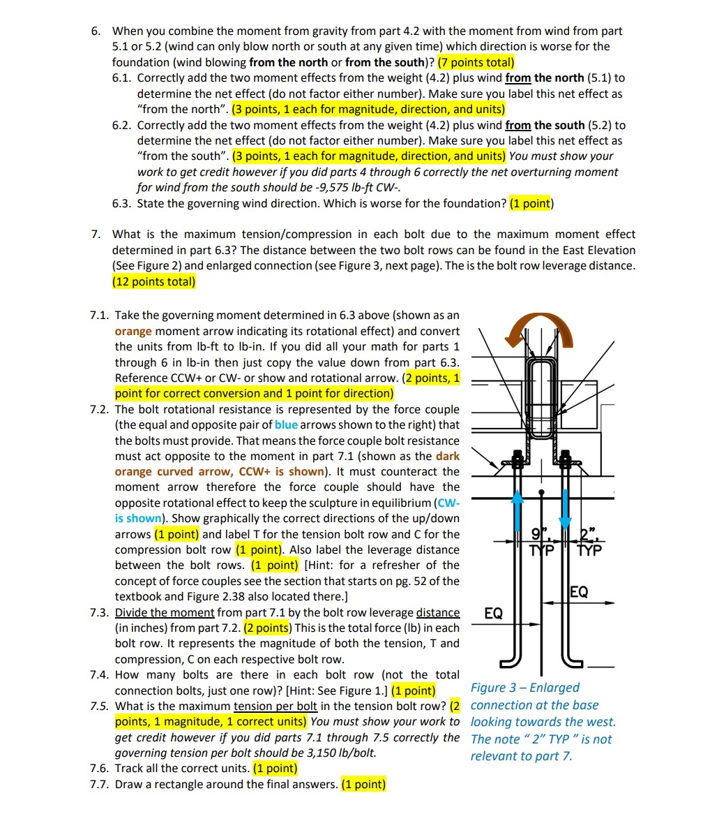
The bolt rotational resistance is represented by the force couple
the equal and opposite pair of blue arrows shown to the right that
the bolts must provide. That means the force couple bolt resistance
must act opposite to the moment in part shown as the dark
orange curved arrow, CCW is shown It must counteract the
moment arrow therefore the force couple should have the
opposite rotational effect to keep the sculpture in equilibrium CW
is shown Show graphically the correct directions of the updown
arrows point and label T for the tension bolt row and C for the
compression bolt row point Also label the leverage distance
between the bolt rows. pointHint: for a refresher of the
concept of force couples see the section that starts on pg of the
textbook and Figure also located there.
Divide the moment from part by the bolt row leverage distance
in inches from part points This is the total force lb in each
bolt row. It represents the magnitude of both the tension, T and
compression, on each respective bolt row.
How many bolts are there in each bolt row not the total
connection bolts, just one rowHint: See Figure point
What is the maximum tension per bolt in the tension bolt row?
points, magnitude, correct units You must show your work to
get credit however if you did parts through correctly the
connection at the base
looking towards the west.
The note TYP is not
governing tension per bolt should be lbbolt
relevant to part
Track all the correct units. point
Draw a rectangle around the final answers. point
Step by Step Solution
There are 3 Steps involved in it
1 Expert Approved Answer
Step: 1 Unlock

Question Has Been Solved by an Expert!
Get step-by-step solutions from verified subject matter experts
Step: 2 Unlock
Step: 3 Unlock