

Question: can you help me to simulate this in breadboarf simulator or tinkercad? hehehe i want to see it virtually College of Computer Studies V. PRACTICE
can you help me to simulate this in breadboarf simulator or tinkercad? hehehe i want to see it virtually
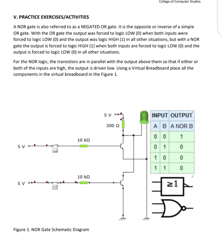
College of Computer Studies V. PRACTICE EXERCISES/ACTIVITIES A NOR gate is also referred to as a NEGATED OR gate. It is the opposite or inverse of a simple OR gate. With the OR gate the output was forced to logic LOW (0) when both inputs were forced to logic LOW (0) and the output was logic HIGH (1) in all other situations, but with a NOR gate the output is forced to logic HIGH (1) when both inputs are forced to logic LOW (0) and the output is forced to logic LOW (0) in all other situations. For the NOR logic, the transistors are in parallel with the output above them so that if either or both of the inputs are high, the output is driven low. Using a Virtual Breadboard place all the components in the virtual breadboard in the Figure 1. 5 V INPUT OUTPUT 2002 A B A NOR B 0 0 1 10 5 V 0 1 0 1 0 0 1 1 0 10 5 VON 21 Figure 1. NOR Gate Schematic Diagram
Step by Step Solution
There are 3 Steps involved in it

Get step-by-step solutions from verified subject matter experts