

Question: Capacitance - PHY 232 Introduction: The purpose of this experiment is to explore basic concepts related to capacitance by investigating how the capacitance of
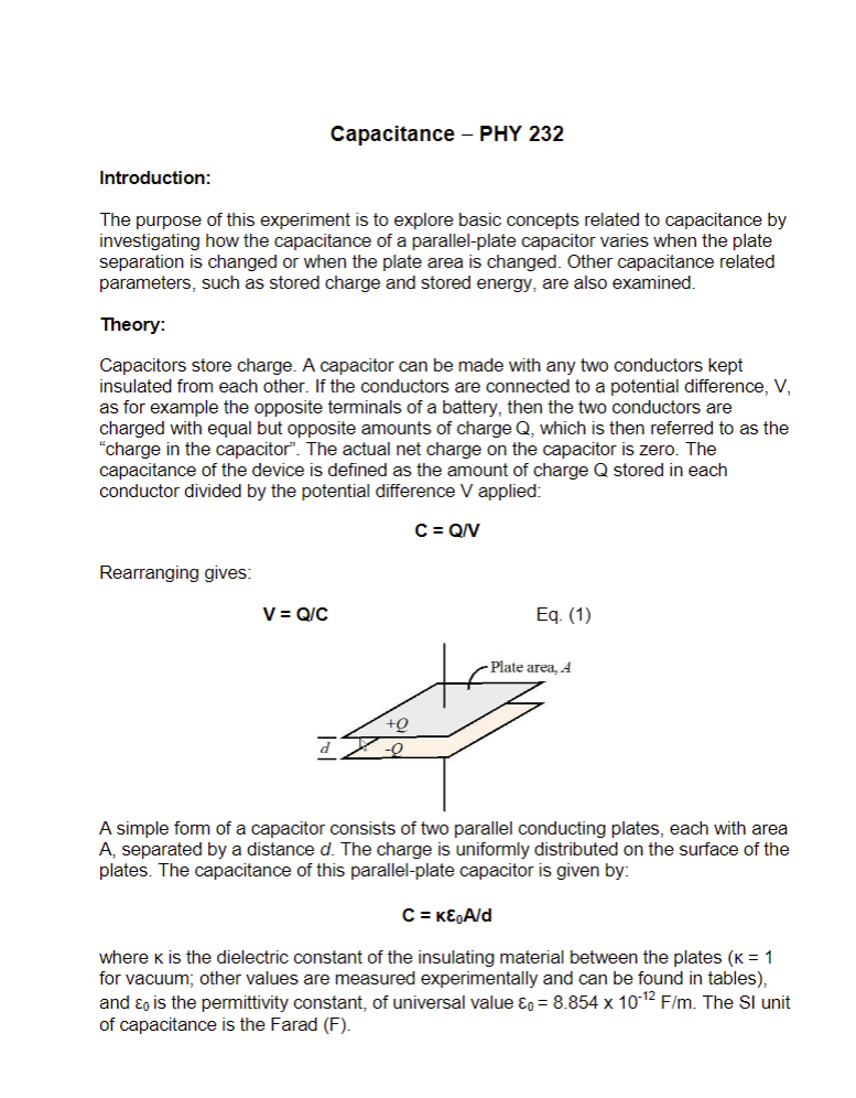
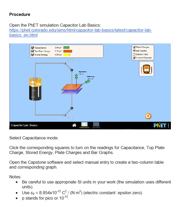
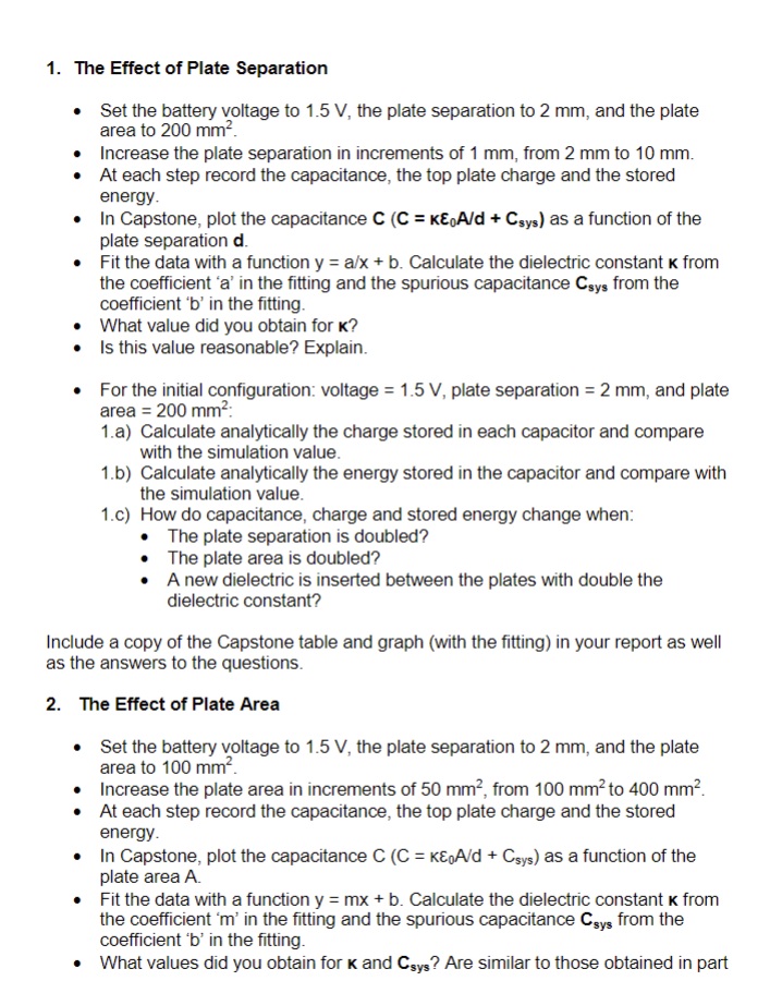
Capacitance - PHY 232 Introduction: The purpose of this experiment is to explore basic concepts related to capacitance by investigating how the capacitance of a parallel-plate capacitor varies when the plate separation is changed or when the plate area is changed. Other capacitance related parameters, such as stored charge and stored energy, are also examined. Theory: Capacitors store charge. A capacitor can be made with any two conductors kept insulated from each other. If the conductors are connected to a potential difference, V, as for example the opposite terminals of a battery, then the two conductors are charged with equal but opposite amounts of charge Q, which is then referred to as the "charge in the capacitor". The actual net charge on the capacitor is zero. The capacitance of the device is defined as the amount of charge Q stored in each conductor divided by the potential difference V applied: Rearranging gives: V = Q/C +Q C = Q/V Eq. (1) -Plate area, A A simple form of a capacitor consists of two parallel conducting plates, each with area A, separated by a distance d. The charge is uniformly distributed on the surface of the plates. The capacitance of this parallel-plate capacitor is given by: C = kA/d where k is the dielectric constant of the insulating material between the plates (K = 1 for vacuum; other values are measured experimentally and can be found in tables), and is the permittivity constant, of universal value & = 8.854 x 10⁻¹² F/m. The SI unit of capacitance is the Farad (F). In a capacitance testing system there could be additional capacitance due to the measurement device and the connecting wires. Sometimes the additional capacitance, which we denote as Csys, cannot be ignored. Including this capacitance, as a capacitor in parallel with the parallel-plate capacitor being tested, gives: C = KA/D + C sys Eq. (2) where Csys is the capacitance of the rest of the system (spurious capacitance). Substitution of Equation 2 into Equation 1 yields: V=Q/ [KEA/d + Csys] Eq. (3) An insulating material placed between the plates of a capacitor will increase its capacitance by a factor called the dielectric constant: C = KC0 Eq. (4) with C = A/d being the capacitance when there is vacuum between the plates of the capacitor. Dielectric materials are non-conductive. Any dielectric material can be used to keep the plates in a capacitor insulated from each other (preventing them from touching and discharging). To three significant figures, k = 1.00 for air. For all other materials, K > 1. If the charge on a capacitor is kept constant while a dielectric is inserted between the plates (the capacitor is not connected to a voltage source), Equations 1 & 4 yield: Q = CV = COV = (C/K) V so V = Vo/K Where Vo is the voltage before inserting the dielectric and V is the voltage after insertion. Since k > 1 always, we have: V Procedure Open the PhET simulation Capacitor Lab Basics: https://phet.colorado.edu/sims/html/capacitor-lab-basics/latest/capacitor-lab- basics en.html Capacitance Top Plate Chienge Storec Energy 0.44 F 0000 0.50 pJ Capacitor Lab: Basics Capecitance Ligh: Bub Plate Charges Bar Graphe Electric Field Current Direction PHET: Select Capacitance mode. Click the corresponding squares to turn on the readings for Capacitance, Top Plate Charge, Stored Energy, Plate Charges and Bar Graphs. Open the Capstone software and select manual entry to create a two-column table and corresponding graph. Notes: Be careful to use appropriate SI units in your work (the simulation uses different units). Use & = 8.85410-12 C/ (N m) (electric constant: epsilon zero). p stands for pico or 10-12 1. The Effect of Plate Separation Set the battery voltage to 1.5 V, the plate separation to 2 mm, and the plate area to 200 mm. Increase the plate separation in increments of 1 mm, from 2 mm to 10 mm. At each step record the capacitance, the top plate charge and the stored energy. In Capstone, plot the capacitance C (C = &A/d + C sys) as a function of the plate separation d. Fit the data with a function y = a/x+b. Calculate the dielectric constant k from the coefficient 'a' in the fitting and the spurious capacitance Csys from the coefficient 'b' in the fitting. What value did you obtain for K? Is this value reasonable? Explain. For the initial configuration: voltage = 1.5 V, plate separation = 2 mm, and plate area = 200 mm: 1.a) Calculate analytically the charge stored in each capacitor and compare with the simulation value. 1.b) Calculate analytically the energy stored in the capacitor and compare with the simulation value. 1.c) How do capacitance, charge and stored energy change when: The plate separation is doubled? The plate area is doubled? A new dielectric is inserted between the plates with double the dielectric constant? Include a copy of the Capstone table and graph (with the fitting) in your report as well as the answers to the questions. 2. The Effect of Plate Area Set the battery voltage to 1.5 V, the plate separation to 2 mm, and the plate area to 100 mm. Increase the plate area in increments of 50 mm, from 100 mm to 400 mm. At each step record the capacitance, the top plate charge and the stored energy. In Capstone, plot the capacitance C (C = KAd + Csys) as a function of the plate area A. Fit the data with a function y = mx + b. Calculate the dielectric constant k from the coefficient 'm' in the fitting and the spurious capacitance C sys from the coefficient 'b' in the fitting. What values did you obtain for K and C sys? Are similar to those obtained in part 1? Are these values reasonable? Explain. Answer the following questions for the initial configuration, voltage = 1.5 V, plate separation = 2 mm, and plate area = 100 mm. 2.a) When you disconnect the battery from the capacitor and insert between the plates a new dielectric with double the dielectric constant: How does capacitance change? How does the voltage between the plates change? How does the stored energy change? Include a copy of the Capstone table and graph (with the fitting) in your report as well as the answers to the questions. 3. Questions 3.a) What is the effect of increasing plate separation on capacitance? 3.b) What is the effect of increasing plate area on capacitance? 3.c) What is the effect of increasing dielectric constant on capacitance? 3.d) What is the minimum number of individual measurements necessary to find the values of the dielectric constant and the spurious capacitance Csys? 3.e) What is the advantage of using the fitting instead of individual measurements to determine the dielectric constant K and the spurious capacitance Csys? 3.f) How would you build a capacitor to maximize the amount of stored charge? What practical limitations do you foresee? Include the answers to these questions in your report.
Step by Step Solution
There are 3 Steps involved in it

Get step-by-step solutions from verified subject matter experts