

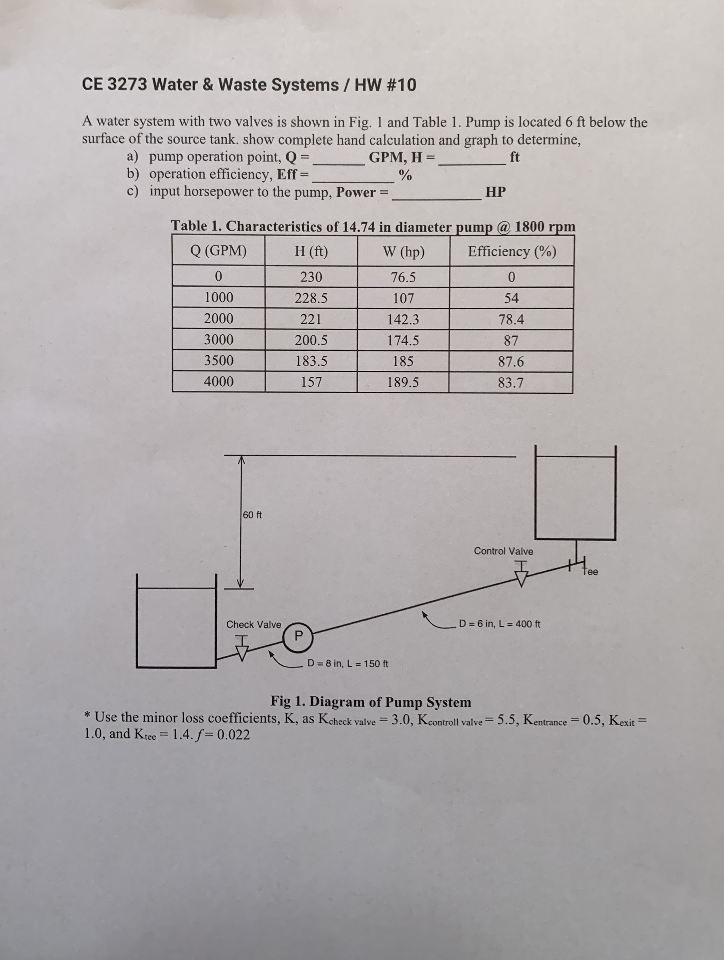
Question: CE 3 2 7 3 Water & Waste Systems / HW # 1 0 A water system with two valves is shown in Fig. 1
CE Water & Waste Systems HW #
A water system with two valves is shown in Fig. and Table Pump is located ft below the surface of the source tank. show complete hand calculation and graph to determine,
a pump operation point,
GPM H
ft
b operation efficiency, Eff
c input horsepower to the pump, Power
HP
Table Characteristics of in diameter pump @ rpm
tableQ GPMEfficiency
Fig Diagram of Pump System
Use the minor loss coefficients, K as and
Step by Step Solution
There are 3 Steps involved in it
1 Expert Approved Answer
Step: 1 Unlock

Question Has Been Solved by an Expert!
Get step-by-step solutions from verified subject matter experts
Step: 2 Unlock
Step: 3 Unlock