

Question: CHAPTER 8 Feeder Load Calculation and Installation 22. Determine the feeder size and other information requested in the following table. The load data to be
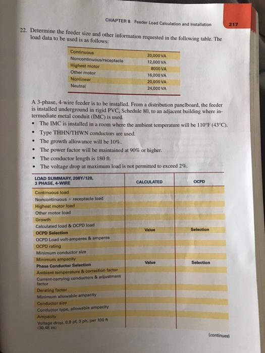
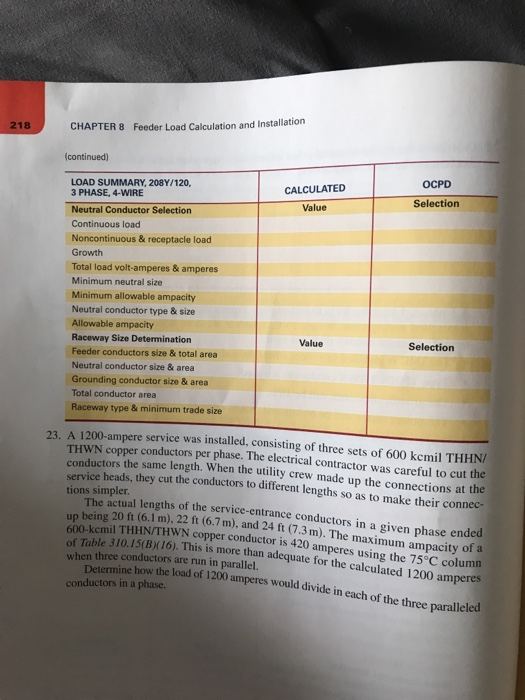
CHAPTER 8 Feeder Load Calculation and Installation 22. Determine the feeder size and other information requested in the following table. The load data to be used is as follows: Continuous Noncontinuous/receptacle Highest motor Other motor Nonlinear Neutral 20,000VA 12,000VA 8000 VA 16,000VA 20,000VA 24,000 VA A 3-phase, 4-wire feeder is to be installed. From a distribution panelboard, the feeder is installed underground in rigid PVC, Schedule 80, to an adjacent building where in- termediate metal conduit (IMC) is used . The IMC is installed in a room where the ambient temperature will be 110F (43C) . Type THHN/THWN conductors are used . "The growth allowance will be 10%. The power factor will be maintained at 90% or higher. The conductor length is 180 ft. The voltage drop at maximum load is not permitted to exceed 2%. LOAD SUMMARY, 208Y/120, 3 PHASE, 4-WIRE Continuous load Noncontinuous + receptacle load Highest motor load Other motor load Growth Calculated load & OCPD load OCPD Selection OCPD Load volt-amperes & amperes OCPD rating Minimum conductor size Minimum ampacity Phase Conductor Selection Ambient temperature & correction factor Current-carrying conductors & adjustment CALCULATED OCPD Value Selection Value Selection factor Derating factor Minimum allowable ampacity Conductor size Conductor type, allowable ampacity Ampacity Voltage drop, 0.9 pf, 3 ph, per 100 ft (30.48 m) continues) lation CHAPTER 8 Feeder Load Calculation and Instal 218 (continued) OCPD LOAD SUMMARY, 208Y/120, 3 PHASE, 4-WIRE CALCULATED Value Selection Neutral Conductor Selection Continuous load Noncontinuous & receptacle load Growth Total load volt-amperes & amperes Minimum neutral size Minimum allowable ampacity Neutral conductor type & size Allowable ampacity Raceway Size Determination Feeder conductors size& total area Neutral conductor size & area Grounding conductor size & area Total conductor area Raceway type & minimum trade size Value Selection service was installed, consisting of three sets of 600 kemil THHN/ conductors per phase. The electrical contractor was careful to cut the ctors the same length. When the utility crew made up the connections at the 23. A 1200-ampere THWN copper condu service heads, they cut the conductors to different lengths so as to make their connec- tions simpler. The actual lengths of the service-entrance conductors in a given phase ended up being 20 ft (6.1 m), 22 ft (6.7 m), and 24 ft (7.3m). The maximum ampacity of a 600-kcmil THHN/THWN copper conductor is 420 amperes using the of Table 310.15(Bx16). This is more than adequate for the calculated 1200 amperes when three conductors are run in parallel. Determine how the load of 1200 amperes conductors in a phase. would divide in each of the three paralle led
Step by Step Solution
There are 3 Steps involved in it

Get step-by-step solutions from verified subject matter experts