Figure 4 shows a possible mesh arrangement around the rivet hole when the plate is subject to
Question:
Figure 4 shows a possible mesh arrangement around the rivet hole when the plate is subject to a force. The mesh is viewed from above. Observe the meshing arrangement shown in figure 4.
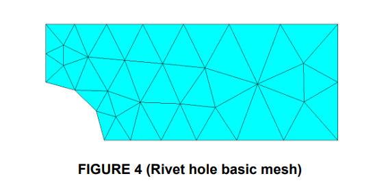
(i) Is it suitable for this application? Give reasons for your answer. (2 marks) (ii) From the diagram, describe where you expect to find the local point of maximum stress. Discuss the stress with regard to element qualities. Is the stress even on the opposite side of rivet? Explain why this is the case and why only a partial model of the geometry, as shown in Figure 4, can give a meaningful answer to the problem. (3 marks) (iii) Discuss how you propose to change the model setup to improve the potential for failure analysis at the point of maximum stress. Mention specific physical criteria you would measure in your answer where possible. Discuss element geometry and size distribution. (5 marks)
Expert Answer: