

Question: Circuit components connected in parallel will always have the same voltage drop across them, but the sum of the currents in each parallel branch must
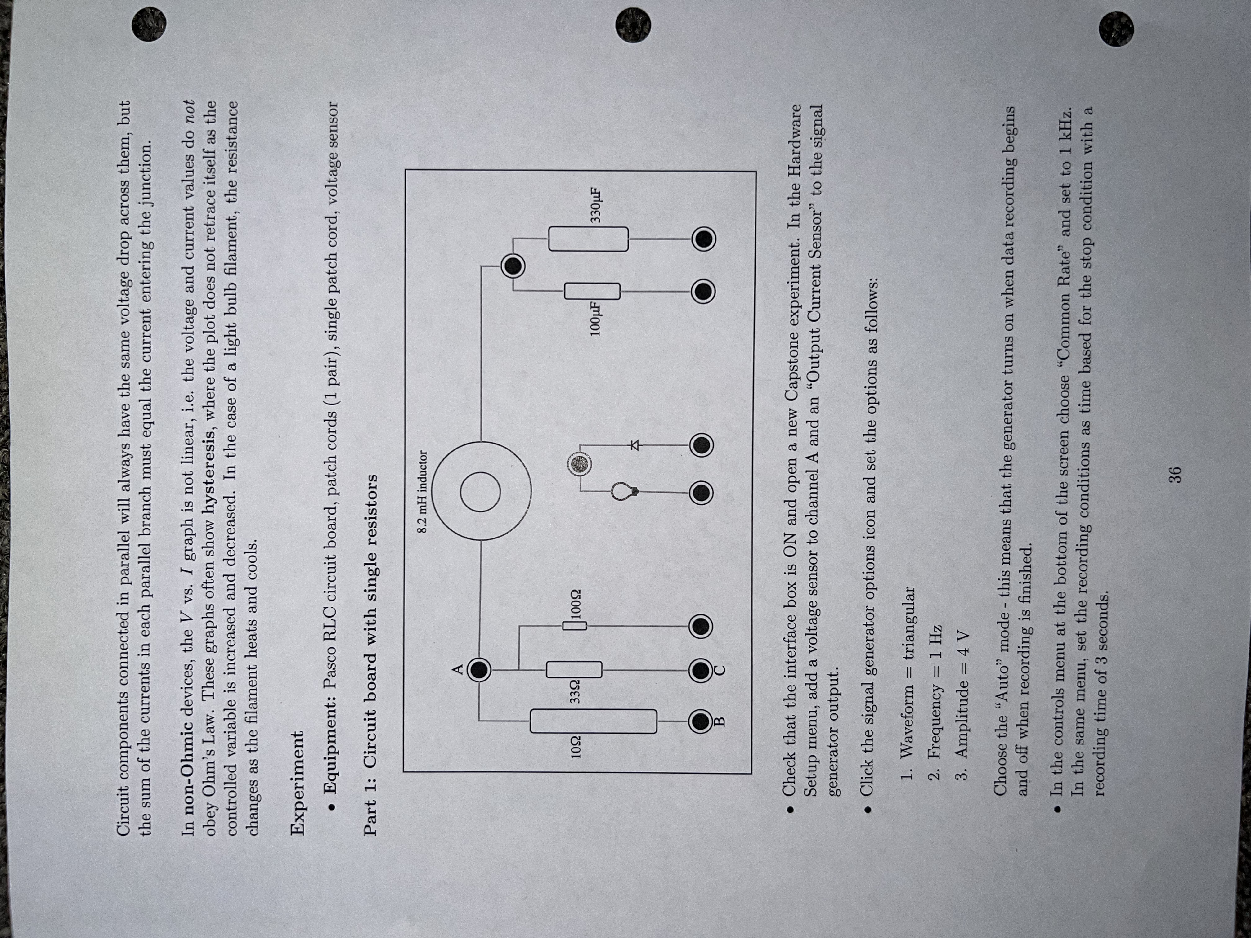

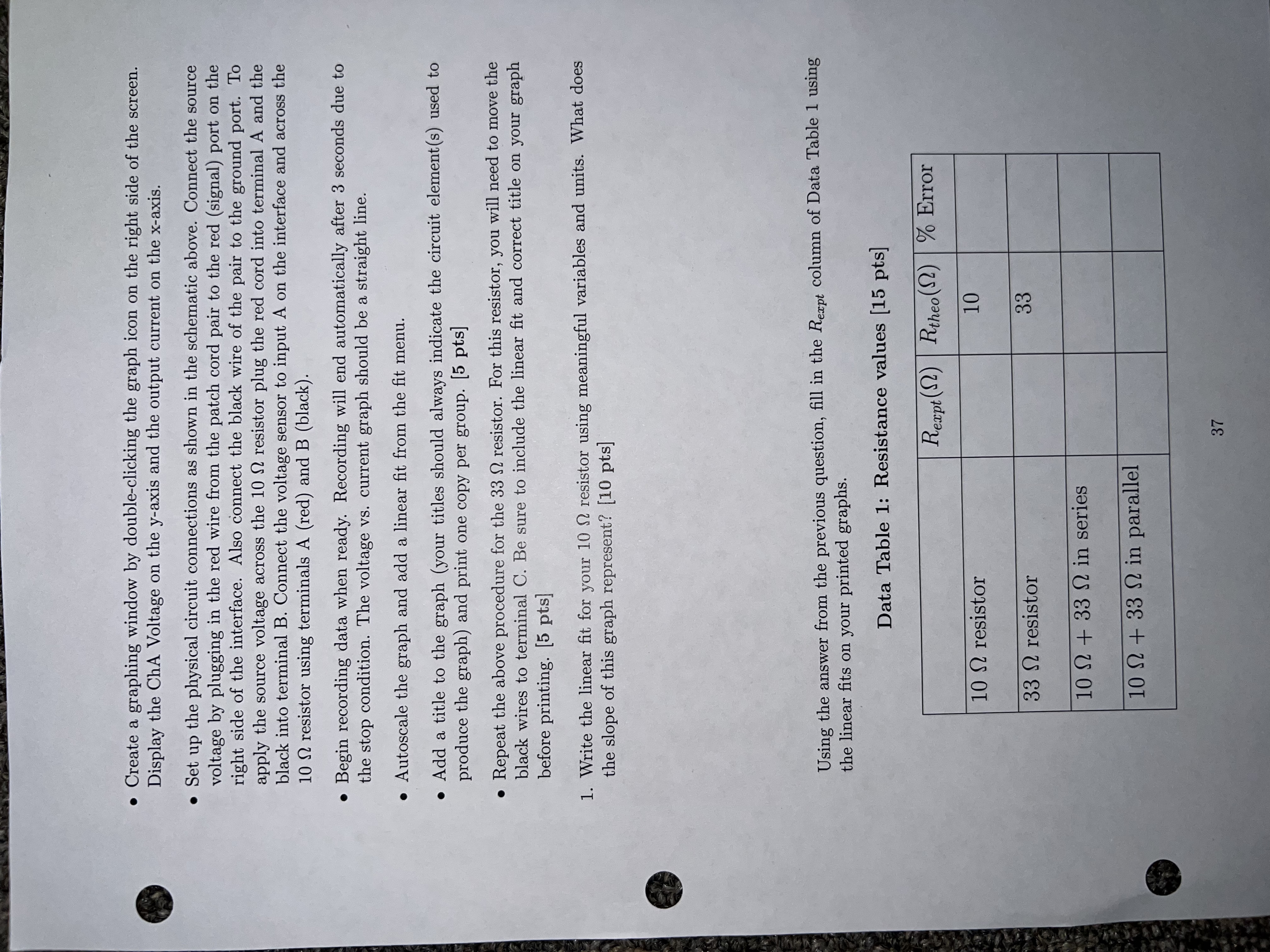

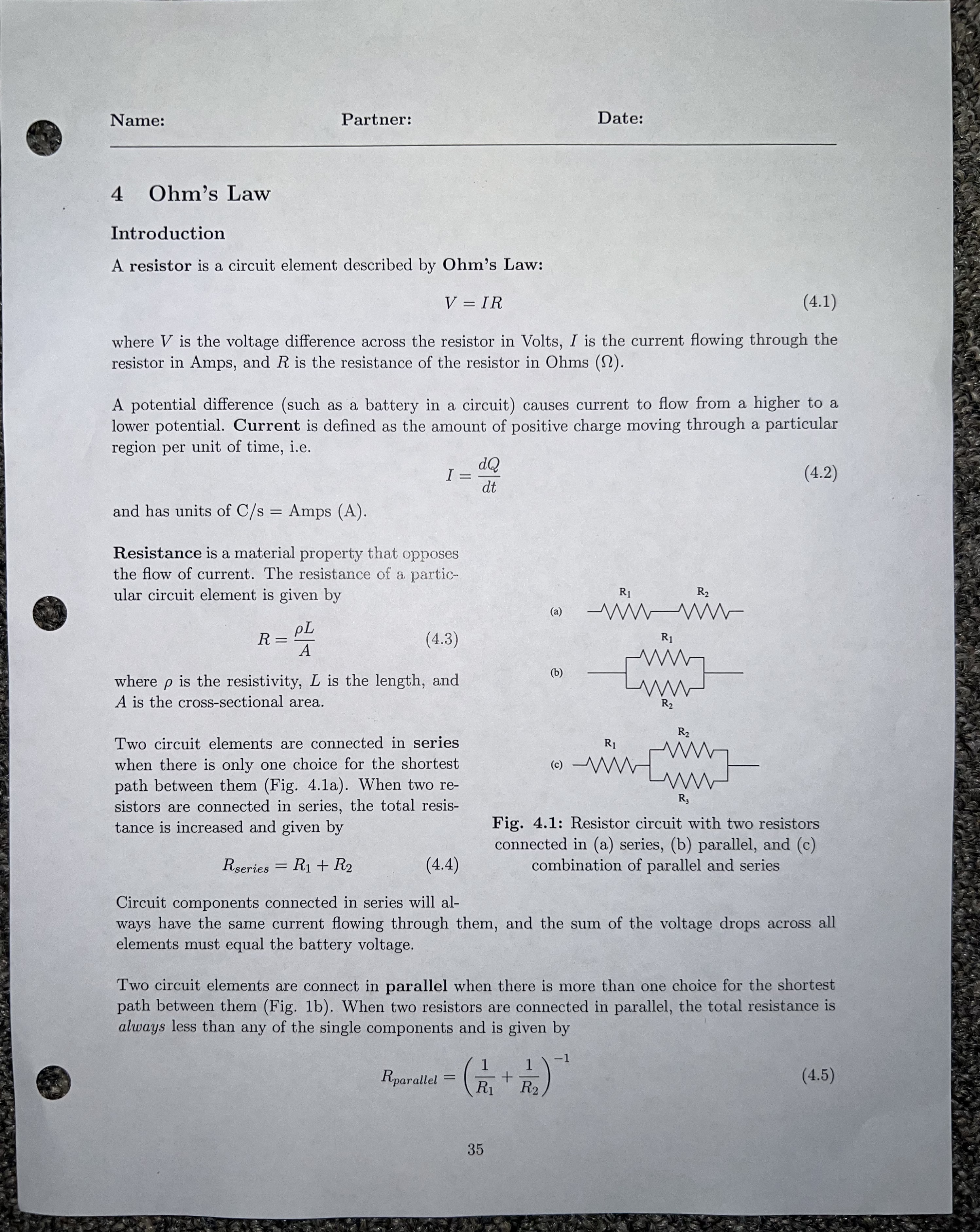

Circuit components connected in parallel will always have the same voltage drop across them, but the sum of the currents in each parallel branch must equal the current entering the junction. In non-Ohmic devices, the V vs. I graph is not linear, i.e. the voltage and current values do not obey Ohm's Law. These graphs often show hysteresis, where the plot does not retrace itself as the controlled variable is increased and decreased. In the case of a light bulb filament, the resistance changes as the filament heats and cools. Experiment . Equipment: Pasco RLC circuit board, patch cords (1 pair), single patch cord, voltage sensor Part 1: Circuit board with single resistors 8.2 mH inductor C 109 339 10082 100 UF 330UF 4 . Check that the interface box is ON and open a new Capstone experiment. In the Hardware Setup menu, add a voltage sensor to channel A and an "Output Current Sensor" to the signal generator output. . Click the signal generator options icon and set the options as follows: 1. Waveform = triangular 2. Frequency = 1 Hz 3. Amplitude = 4 V Choose the "Auto" mode - this means that the generator turns on when data recording begins and off when recording is finished. . In the controls menu at the bottom of the screen choose "Common Rate" and set to 1 kHz. In the same menu, set the recording conditions as time based for the stop condition with a recording time of 3 seconds. 36Part 2: Circuit board with resistors in series and parallel . Rearrange the source and voltage sensor wires so that the 10 2 and 33 0 resistors are in SERIES. Check with your lab instructor to verify that your setup is correct. . Record a data run and add a linear fit. Use your results from question 1 to add the total resistance of this circuit to Data Table 1. . Now set up the circuit so that the 10 0 and 33 2 resistors are in PARALLEL. To do this you will need to add a jumper cord (the single patch cord at your station). . Record a data run and add a linear fit. Use your results from question 1 to add the total resistance of this circuit to Data Table 1. 2. Calculate the theoretical resistance of the resistors in series and parallel using the equations given in the Introduction. Use the Rexpt values for the resistance of each individual resistor in your calculations. Show your calculations and record your answers in Data Table 1. [10 pts] 3. Calculate the percent error for each resistor and combination and record in Data Table 1. Show your calculations below. [5 pts] 38. Create a graphing window by double-clicking the graph icon on the right side of the screen. Display the ChA Voltage on the y-axis and the output current on the x-axis. . Set up the physical circuit connections as shown in the schematic above. Connect the source voltage by plugging in the red wire from the patch cord pair to the red (signal) port on the right side of the interface. Also connect the black wire of the pair to the ground port. To apply the source voltage across the 10 2 resistor plug the red cord into terminal A and the black into terminal B. Connect the voltage sensor to input A on the interface and across the 10 n resistor using terminals A (red) and B (black). . Begin recording data when ready. Recording will end automatically after 3 seconds due to the stop condition. The voltage vs. current graph should be a straight line. . Autoscale the graph and add a linear fit from the fit menu. . Add a title to the graph (your titles should always indicate the circuit element(s) used to produce the graph) and print one copy per group. [5 pts] . Repeat the above procedure for the 33 0 resistor. For this resistor, you will need to move the black wires to terminal C. Be sure to include the linear fit and correct title on your graph before printing. [5 pts] 1. Write the linear fit for your 10 0 resistor using meaningful variables and units. What does the slope of this graph represent? [10 pts] Using the answer from the previous question, fill in the Rexpt column of Data Table 1 using the linear fits on your printed graphs. Data Table 1: Resistance values [15 pts] Rexpt () Rtheo () |% Error 10 0 resistor 10 33 0 resistor 33 10 0 + 33 0 in series 10 0 + 33 0 in parallel 37Results and Conclusions (20 pts) Briefly summarize the objective of today's lab as well as the results of your experiment. State any applicable errors you calculated and give AT LEAST two possible reasons your results deviated from theoretical values. If the experiment was purely qualitative (i.e. you did not calculate a % difference or % error), you may replace the two sources of error with two SPECIFIC concepts from lecture that the experiment demonstrated. Objective: Results: Report part 2 results and the percent error / difference of the experiment Sources of error: The deviation of our measurements from theory could be attributed to 1. 2. Note - the following are never acceptable sources of error: "human error" . rounding/ calculation errors . mysterious equipment malfunction 40Name: Partner: Date: 4 Ohm's Law Introduction A resistor is a circuit element described by Ohm's Law: V = IR (4.1) where V is the voltage difference across the resistor in Volts, I is the current owing through the resistor in Amps, and R is the resistance of the resistor in Ohms (Q). A potential difference (such as a battery in a circuit) causes current to ow from a higher to a lower potential. Current is dened as the amount of positive charge moving through a particular region per unit of time, i.e. r dQ I _ 2,, (4.2) and has units of 0/5 2 Amps (A). Resistance is a material property ths l- \"mu hses the ow of current. The resistance of a partio ular circuit element is given by R1 R2
Step by Step Solution
There are 3 Steps involved in it

Get step-by-step solutions from verified subject matter experts