

Question: CIRCULAR SECTIONS Aims: To examine the relationship between torque and angular deflection of a solid circular section and how the properties of the material affect
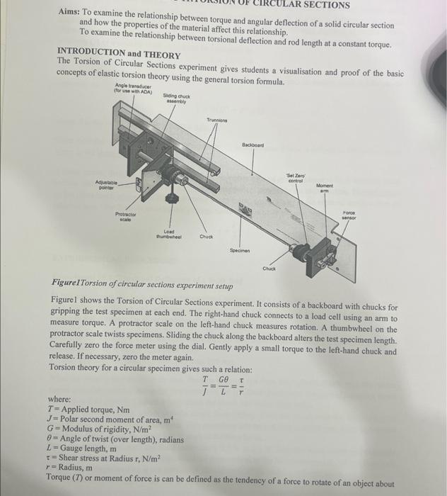
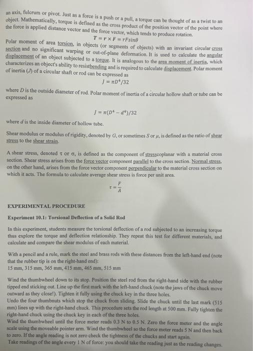
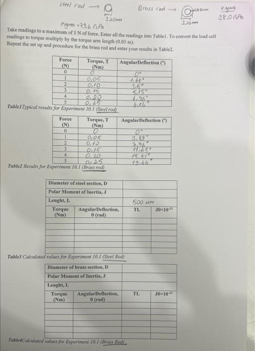
CIRCULAR SECTIONS Aims: To examine the relationship between torque and angular deflection of a solid circular section and how the properties of the material affect this relationship. To examine the relationship between torsional deflection and rod length at a constant torque. INTRODUCTION and THEORY The Torsion of Circular Sections experiment gives students a visualisation and proof of the basic concepts of elastic torsion theory using the general torsinn fromul. Figure cursion of curcuar sectoons experiment setup Figurel shows the Torsion of Circular Sections experiment. It consists of a backboard with chucks for gripping the test specimen at each end. The right-hand chuck connects to a load cell using an arm to measure torque. A protractor scale on the left-hand chuck measures rotation. A thumbwheel on the protractor scale twists specimens. Sliding the chuck along the backboard alters the test specimen length. Carefully zero the force meter using the dial. Gently apply a small torque to the left-hand chuck and release. If necessary, zero the meter again. Torsion theory for a circular specimen gives such a relation: where: JT=LG=r T= Applied torque, Nm J= Polar second moment of area, m4 G= Modulus of rigidity, N/m2 = Angle of twist (over length), radians L= Gauge length, m = Shear stress at Radius r,N/m2 an axis, fulcrum or pivot. Just as a force is a push or a pull, a torque can be thought of as a twist to an object. Mathematically, torque is defined as the cross product of the position vector of the point where the force is applied distance vector and the force vector, which tends to produce rotation. T=rF=rFsin Polar moment of area torsion, in objects (or segments of ebjects) with an invariant circular cross section and no significant warping or out-of-plane deformation. It is used to calculate the angular displacement of an object subjected to a torgue. It is analogous to the area moment of inertia, which characterizes an object's ability to resistbending and is required to calculate displacement. Polar moment of inertia (J) of a circular shaft or rod can be expressed as J=D4/32 where D is the outside diameter of rod. Polar moment of inertia of a circular hollow shaft or tube can be expressed as J=(D4d4)/32 where d is the inside diameter of hollow tube. Shear modulus or modulus of rigidity, denoted by G, or sometimes S or , is defined as the ratio of shear stress to the thear strain. A shear stress, denoted or , is defined as the component of stresscoplanar with a material cross. section. Shear stress arises from the force vector component parallel to the cross section. Normal stress. on the other hand, arises from the force vector component perpendicular to the material cross section on which it ucts. The formula to calculate average shear stress is force per unit area. =AF EXPERIMENTAL PROCEDURE Experiment 10.1: Torsioaal Deflection of a Solid Rod In this experiment, students measure the torsional deflection of a rod subjected to an increasing torque thus explore the torque and deflection relationship. They repeat this test for different materials, and calculate and compare the shear modulus of each material. With a pencil and a rule, mark the steel and brass rods with these distances from the leth-hand end (note that the rubber tip is on the right-hand end): is mm, 315mm,365mm,415mm,465mm,515mm Wind the thumbwheel down to its stop. Position the steel rod from the right-hand side with the rubber tipped end sticking out. Line up the fint mark with the left-hand chuck (note the jaws of the chuck move outward as they elose!). Tighten it fully using the chuck key in the three holes. Undo the four thumbnuts which stop the chuck from sliding. Stide the chuck until the last mark (515 mm) lines up with the righthand chuck. This procedure sets the rod length at 500mm. Fully tighten the right-hand chuck using the chuck key in euch of the three holes. Wind the thumbwheel until the force meter reads 0.3N to 0.5N. Zero the force meter and the angle scale using the moveable pointer arm. Wind the thumbwheel so the force meter reads 5N and then back to zero. If the angle reading is not zero check the tightness of the chucks and start again. Take rendings of the angle every 1N of force: you should talie the reading just as the reading changes. Take readings to a maximum of 5N of force. Enter all the resdings into Tablel. To convert the load cell readings to torque multiply by the torqoe arm length (0.05m). Repeat the set up and procedere for the brass rod and enter your resules in Tabie2. TableITypical resul Table2 Reruilts for E TablesCaiculate. Results and Discussions for Experiment 10.1 1. Establish the TL and J values and complete Table 3 and Tablo4. Plot a graph of TL against JA. Evaluate the modulus of rigidity for both steel and brass rods. Remember you must convert your angle measurements from degrees to radians (2 radians =360). 2. Examine the torsion formula and say what the value of the gradient represents. Does the value compare favourably with typical ones
Step by Step Solution
There are 3 Steps involved in it

Get step-by-step solutions from verified subject matter experts