

Question: Clippers and Clampers, can you simulate this in multisim please,I need to see the simulation screenshot for the 2 procedure withgraphsthese are the 2 procedures
Clippers and Clampers, can you simulate this in multisim please,I need to see the simulation screenshot for the 2 procedure withgraphsthese are the 2 procedures 
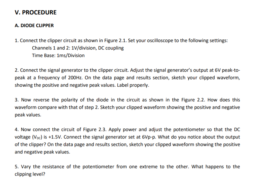
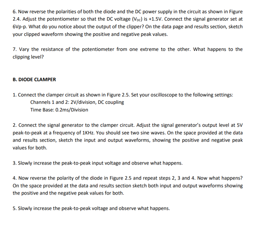
I. OBJECTIVE To investigate the clipping and clamping of sinusoidal signal using silicon diode. II. BASIC CONCEPT EXPERIMENT 8: CLIPPERS AND CLAMPERS Diode can be used in wave-shaping circuit that limits a portion of a signal or shift the dc voltage level. These are the diode clipper and the diode clamper are examples of wave-shaping circuit. The diode clipper prevents the output voltage from exceeding a given value. It clips those portions of a signal that are above or below the reference level. The diode clamper circuit shifts the entire waveform by a dc level without changing the original waveform. III. MATERIALS Quantity 1 2 1 1 1 1 1 1 1 1set Description 15-KO resistor (1/2 watt) 1N4001 silicon diode 5 KQ Potentiometer or 10-Turn Trimpot 1 uF (16V) Breadboard Dual Trace Oscilliscope Power Supply Signal Generator Multimeter Connecting wires V. PROCEDURE A. DIODE CLIPPER 1. Connect the clipper circuit as shown in Figure 2.1. Set your oscilloscope to the following settings: Channels 1 and 2: 1V/division, DC coupling Time Base: 1ms/Division 2. Connect the signal generator to the clipper circuit. Adjust the signal generator s output at 6V peak-to- peak at a frequency of 200Hz. On the data page and results section, sketch your clipped waveform, showing the positive and negative peak values. Label properly. 3. Now reverse the polarity of the diode in the circuit as shown in the Figure 2.2. How does this waveform compare with that of step 2. Sketch your clipped waveform showing the positive and negative peak values. 4. Now connect the circuit of Figure 2.3. Apply power and adjust the potentiometer so that the DC voltage (Voc) is +1.5V. Connect the signal generator set at 6Vp-p. What do you notice about the output of the clipper? On the data page and results section, sketch your clipped waveform showing the positive and negative peak values. 5. Vary the resistance of the potentiometer from one extreme to the other. What happens to the clipping level? 6. Now reverse the polarities of both the diode and the DC power supply in the circuit as shown in Figure 2.4. Adjust the potentiometer so that the DC voltage (Voc) is +1.5V. Connect the signal generator set at 6Vp-p. What do you notice about the output of the clipper? On the data page and results section, sketch your clipped waveform showing the positive and negative peak values. 7. Vary the resistance of the potentiometer from one extreme to the other. What happens to the clipping level? B. DIODE CLAMPER 1. Connect the clamper circuit as shown in Figure 2.5. Set your oscilloscope to the following settings: Channels 1 and 2: 2V/division, DC coupling Time Base: 0.2ms/Division 2. Connect the signal generator to the clamper circuit. Adjust the signal generator s output level at 5V peak-to-peak at a frequency of 1KHz. You should see two sine waves. On the space provided at the data and results section, sketch the input and output waveforms, showing the positive and negative peak values for both. 3. Slowly increase the peak-to-peak input voltage and observe what happens. 4. Now reverse the polarity of the diode in Figure 2.5 and repeat steps 2, 3 and 4. Now what happens? On the space provided at the data and results section sketch both input and output waveforms showing the positive and the negative peak values for both. 5. Slowly increase the peak-to-peak voltage and observe what happens.
Step by Step Solution
3.32 Rating (152 Votes )
There are 3 Steps involved in it
Diode Clipper Simulation Setup Circuit Construct the diode clipper circuit according to Figure 21 in MultiSim Use a 15k resistor a 1N4001 diode a sign... View full answer

Get step-by-step solutions from verified subject matter experts