

Question: CODE IS EASY, just need to confirm and double check. Will upvote! I have a verilog code on visual studio. I am using this code,
CODE IS EASY, just need to confirm and double check. Will upvote!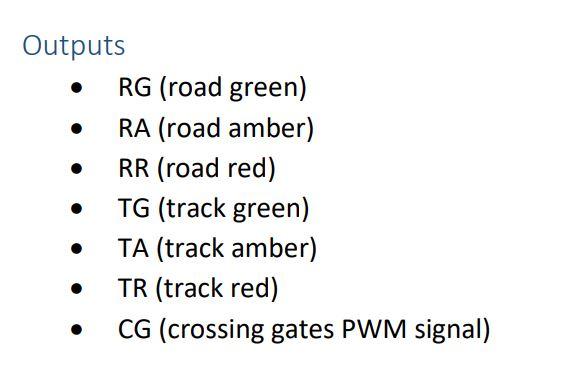
I have a verilog code on visual studio. I am using this code, because it is a similar task. Though some specifications are different. If you could please rearrange the code as needed in task. I have already updated my code a lot, but Id like to use this as reference once again. Time delay for train to pass X seconds should be 2sec. The time delay on amber 1/Y seconds, should be 5 sec, so 1/5sec. Other than that change the name from highway to mainroad and farm to railway, also include the amber light code parts, change colour if needed. Also do please upload waveforms which show the purpose and working of this traffic signal. Highly appreciated. Preferably use visual studio if possible.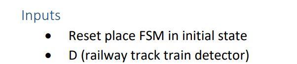 Here is the code.v-
// fpga4student.com FPGA projects, VHDL projects, Verilog projects // Verilog project: Verilog code for traffic light controller module traffic_light(light_highway, light_farm, C, clk, rst_n); parameter HGRE_FRED=2'b00, // Highway green and farm red HYEL_FRED = 2'b01,// Highway yellow and farm red HRED_FGRE=2'b10,// Highway red and farm green HRED_FYEL=2'b11;// Highway red and farm yellow input C, // sensor clk, // clock = 50 MHz rst_n; // reset active low output reg[2:0] light_highway, light_farm; // output of lights // fpga4student.com FPGA projects, VHDL projects, Verilog projects reg[27:0] count=0,count_delay=0; reg delay10s=0, delay3s1=0,delay3s2=0,RED_count_en=0,YELLOW_count_en1=0,YELLOW_count_en2=0; wire clk_enable; // clock enable signal for 1s reg[1:0] state, next_state; // next state always @(posedge clk or negedge rst_n) begin if(~rst_n) state green else next_state =HGRE_FRED; end HYEL_FRED: begin// yellow on highway and red on farm way light_highway = 3'b010; light_farm = 3'b100; RED_count_en=0; YELLOW_count_en1=1; YELLOW_count_en2=0; if(delay3s1) next_state = HRED_FGRE; // yellow for 3s, then red else next_state = HYEL_FRED; end HRED_FGRE: begin// red on highway and green on farm way light_highway = 3'b100; light_farm = 3'b001; RED_count_en=1; YELLOW_count_en1=0; YELLOW_count_en2=0; if(delay10s) next_state = HRED_FYEL; // red in 10s then turn to yello -> green again for high way else next_state =HRED_FGRE; end HRED_FYEL:begin// red on highway and yellow on farm way light_highway = 3'b100; light_farm = 3'b010; RED_count_en=0; YELLOW_count_en1=0; YELLOW_count_en2=1; if(delay3s2) next_state = HGRE_FRED; // turn green for highway, red for farm road else next_state =HRED_FYEL; end default: next_state = HGRE_FRED; endcase end // fpga4student.com FPGA projects, VHDL projects, Verilog projects // create red and yellow delay counts always @(posedge clk) begin if(clk_enable==1) begin if(RED_count_en||YELLOW_count_en1||YELLOW_count_en2) count_delayand code_tb.v
// fpga4student.com FPGA projects, VHDL projects, Verilog project // Verilog project: Verilog code for traffic light controller `timescale 10 ns/ 1 ps // 2. Preprocessor Directives `define DELAY 1 // 3. Include Statements //`include "counter_define.h" module tb_traffic; // 4. Parameter definitions parameter ENDTIME = 400000; // 5. DUT Input regs //integer count, count1, a; reg clk; reg rst_n; reg sensor; wire [2:0] light_farm; // 6. DUT Output wires wire [2:0] light_highway; // fpga4student.com FPGA projects, VHDL projects, Verilog projects // 7. DUT Instantiation traffic_light tb(light_highway, light_farm, sensor, clk, rst_n); // 8. Initial Conditions initial begin clk = 1'b0; rst_n = 1'b0; sensor = 1'b0; // count = 0; //// count1=0; // a=0; end // 9. Generating Test Vectors initial begin main; end task main; fork clock_gen; reset_gen; operation_flow; debug_output; endsimulation; join endtask task clock_gen; begin forever #`DELAY clk = !clk; end endtask task reset_gen; begin rst_n = 0; # 20 rst_n = 1; end endtask // fpga4student.com FPGA projects, VHDL projects, Verilog projects task operation_flow; begin sensor = 0; # 600 sensor = 1; # 1200 sensor = 0; # 1200 sensor = 1; end endtask // 10. Debug output task debug_output; begin $display("----------------------------------------------"); $display("------------------ -----------------------"); $display("----------- SIMULATION RESULT ----------------"); $display("-------------- -------------------"); $display("---------------- ---------------------"); $display("----------------------------------------------"); $monitor("TIME = %d, reset = %b, sensor = %b, light of highway = %h, light of farm road = %h",$time,rst_n ,sensor,light_highway,light_farm ); end endtask // fpga4student.com FPGA projects, VHDL projects, Verilog projects //12. Determines the simulation limit task endsimulation; begin #ENDTIME $display("-------------- THE SIMUALTION END ------------"); $finish; end endtask endmodule
THANK YOU!!!
. Outputs RG (road green) RA (road amber) RR (road red) TG (track green) TA (track amber) TR (track red) CG (crossing gates PWM signal) . Inputs Reset place FSM in initial state D (railway track train detector) . Outputs RG (road green) RA (road amber) RR (road red) TG (track green) TA (track amber) TR (track red) CG (crossing gates PWM signal) . Inputs Reset place FSM in initial state D (railway track train detector)
Step by Step Solution
There are 3 Steps involved in it

Get step-by-step solutions from verified subject matter experts