

Question: COMPACTNESS and EFFECTIVE SECTION MODULUS Question: Verify the compactness and Z ex and Z ey values of section 500 WC 228 Grade 400 (Note: 7
COMPACTNESS and EFFECTIVE SECTION MODULUS
Question: Verify the compactness and Zex and Zey values of section 500 WC 228 Grade 400 (Note: 7 th Edition Hot Rolled Structural Steel Products)
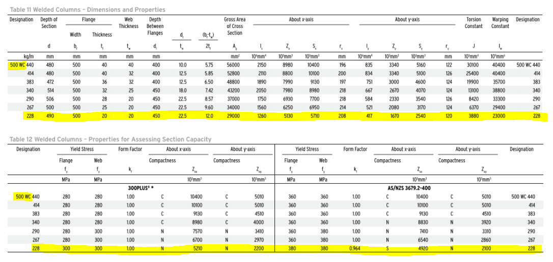
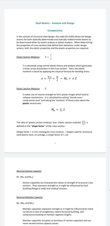
Notes about the question: The member Highlighted in yellow in both Table 11 & 12 (First photo) is the one in reference to the question (500 WC 228 Grade 400)
The rest of the photos are equations used to solve the question
Also this is for my class design of steel structures for civil engineering
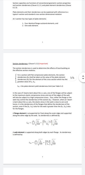
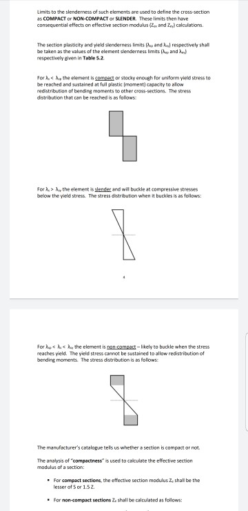
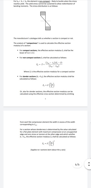
About x-axis Table 11 Welded Columns - Dimensions and Properties Designation Depth of Flange Web Depth Section Thickness Between Width Thickness Flanges About yaxis Gross Area of Cross Section Torsion Constant Warping Designation Constant d ale (b, 2t, d t t d t A J mm mm mm 480 mm mm 500 $ 10 mm 5160 mm 196 40 400 575 kg/m 500 WC 440 414 383 340 290 267 228 40 40 36 32 400 400 450 mm 56000 52800 48800 43200 5.85 6.50 7.42 S 10 mm 10400 10100 9130 8980 100 125 12.5 18.0 225 225 22.5 1 10mm 2150 2110 1890 2050 1750 1560 1260 200 197 218 2 10 mm 8980 8800 7990 7980 6930 6250 10 mm 835 834 751 667 480 472 514 506 500 490 500 500 500 500 500 500 122 126 124 124 32 32 25 20 20 20 10 mm 30100 25400 19900 13100 10 mm 3340 3340 3000 2670 2330 2080 1670 5100 4600 4070 3540 3170 2540 10 mm 40400 40400 35700 38800 33300 29400 23000 500 WC 440 414 383 340 290 267 228 28 8.57 7700 218 584 126 25 20 450 450 450 9.60 12.0 37000 34000 29000 6950 5710 521 417 124 120 8420 6370 3880 5130 208 Yield Stress Form Factor About x-axis About y-axis Designation Web Compactness Flange f MPa K Z 10 mm MPa Table 12 Welded Columns - Properties for Assessing Section Capacity Designation Yield Stress Form Factor About x-axis About y-axis Flange Web Compactness Compactness f f k 2. Z 2 MPa MPa 10 mm 10 mm 300PLUS 500 WC 440 280 280 100 C 10400 C 5010 414 280 280 100 10100 C 5010 383 280 280 100 9130 C 4510 340 280 280 100 8980 4000 290 280 300 1.00 N 7570 N 3410 267 280 300 100 N 6700 N 2970 228 300 300 100 N 5210 N 2200 Compactness z 10 mm AS/NZS 3679.2-400 10400 10100 C 9130 N 8830 5010 1.00 1.00 360 360 360 360 500 WC 440 414 360 360 360 360 C 1.00 1.00 5010 4510 3920 3310 2860 383 340 N 1.00 N N 290 360 360 380 380 380 380 N 7410 6540 4920 N 1.00 0.964 267 S N 2100 228 Steel Beams - Analysis and Design Compactness In the content of structural steel design, the code (AS 4100) allows the design actions for both statically determinate and statically indeterminate beams to be determined either by elastic analysis or plastic analysis. When determining the properties of cross sections that define their behaviour under design actions, both the elastic properties and the plastic properties are required. Elastic Section Modulus: Z is calculated using normal elastic theory and analysis which generates a linear stress distribution in the cross section. Then, the elastic moment is found by applying the dassical formula for bending stress o = = - M. = 62 Plastic Section Modulus 5 Smakes use of reserve strength to form plastic hinges which lead to collapse mechanisms. It is calculated by setting tensileares = compressive area and taking the moment of those areas about the plastic neutral axis. M = lys The ratio of plastic section modulus' over 'elestic section modules ) defined as the "shape factor of the cross-section (Shape factor - 1.5 for rectangular cross sections. l-shapes used for structural steel beams have, on average, a shape factor of 1.12). Nominal Section Capacity M. IM. and M.) Section capacities are characteristic values of strength of structural cross sections. They represent strength as it might be influenced by local buckling Iflange or web) and residual stresses. Nominal Member Capacity M (Me and My) Member capacities represent strength as it might be influenced by initial curvature or lack of straightness, lateral torsional buckling and compressive buckling of member segment lengths. Member capacities are given as functions of section capacities and can never exceed section capacity values. Section capacities are functions of conventional geometric section properties and section slenderness (Clause 5.2.2.) and plate element slenderness (Clause 62.3). Plate elements and their slenderness can be explained with reference to a typicall-section and standard cross-section dimensional notation: An t-section has two types of plate elements: 1. Four identical flange outstand elements, and 2. One web element Section slenderness (Clause 5.2.2) Important The section slenderness is used to determine the effects of local buckling on the effective section modulus. For a section with flat compression plate elements, the section slenderness (.) shall be taken as the value of the plate element 3/6 Slenderness (1) for the element of the cross-section which has the greatest value of Life for the plate element yield slenderness limit (see Table 5.2) In the case of 1 beams bent about the x-X axis, one of the flanges will be subject to the maximum elastic compressive stress and one of the edges of the web will also be subject to a high compressive stress. Thus, either the flange or the web may control the slenderness of the section (2). However, when an I beam is bent about the y-yaxis, the elastic stress in the web is close to zero and hence, it is the slendemess of the flanges that define the slenderness of the Section, even if the hehe) ratio for the web is greater than the ratio for the flanges. A flange element is unsupported for free) along the outer edge and supported along the other edge by the web. Its slenderness is defined by: in e) - 51 250 250 A web element is supported along both edges by each flange. Its slenderness is defined by --01-19 250 Limits to the slenderness of such elements are used to define the cross-section as COMPACT OF NON-COMPACT OF SLENDER. These limits then have consequential effects on effective section modulus (Zeand Ze) calculations. The section plasticity and yield slenderness limits and respectively shall be taken as the values of the element slenderness limits and le respectively given in Table 5.2 For .y the element is slender and wil buckle at compressive stresses below the yield stress. The stress distribution when it buckles is as follows: For le
Step by Step Solution
There are 3 Steps involved in it
To verify the compactness and effective section modulus Zex and Zey of the 500 WC 228 Grade 400 section follow these steps 1 Check Compactness Table R... View full answer

Get step-by-step solutions from verified subject matter experts