

Question: Consider a synchronous circuit where every clock cycle an n-bit RCA adder (section 15.2) is used to increment (+1) an n-bit register value. This circuit
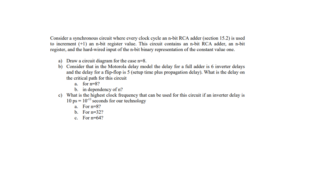
Consider a synchronous circuit where every clock cycle an n-bit RCA adder (section 15.2) is used to increment (+1) an n-bit register value. This circuit contains an n-bit RCA adder, an n-bit register, and the hard-wired input of the n-bit binary representation of the constant value one a) Draw a circuit diagram for the case n=8 b) Consider that in the Motorola delay model the delay for a full adder is 6 inverter delays and the delay for a flip-flop is 5 (setup time plus propagation delay). What is the delay on the critical path for this circuit for n-8? in dependency of n? a. b. c) What is the highest clock frequency that can be used for this circuit if an inverter delay is 10 ps-10 seconds for our technology a. b. c. For n=8 ? For n-32? For n-64? Consider a synchronous circuit where every clock cycle an n-bit RCA adder (section 15.2) is used to increment (+1) an n-bit register value. This circuit contains an n-bit RCA adder, an n-bit register, and the hard-wired input of the n-bit binary representation of the constant value one a) Draw a circuit diagram for the case n=8 b) Consider that in the Motorola delay model the delay for a full adder is 6 inverter delays and the delay for a flip-flop is 5 (setup time plus propagation delay). What is the delay on the critical path for this circuit for n-8? in dependency of n? a. b. c) What is the highest clock frequency that can be used for this circuit if an inverter delay is 10 ps-10 seconds for our technology a. b. c. For n=8 ? For n-32? For n-64
Step by Step Solution
There are 3 Steps involved in it

Get step-by-step solutions from verified subject matter experts