

Question: Consider a system with the one - line diagram shown in Figure E 5 . 1 4 ( a ) . The threephase transformer nameplate
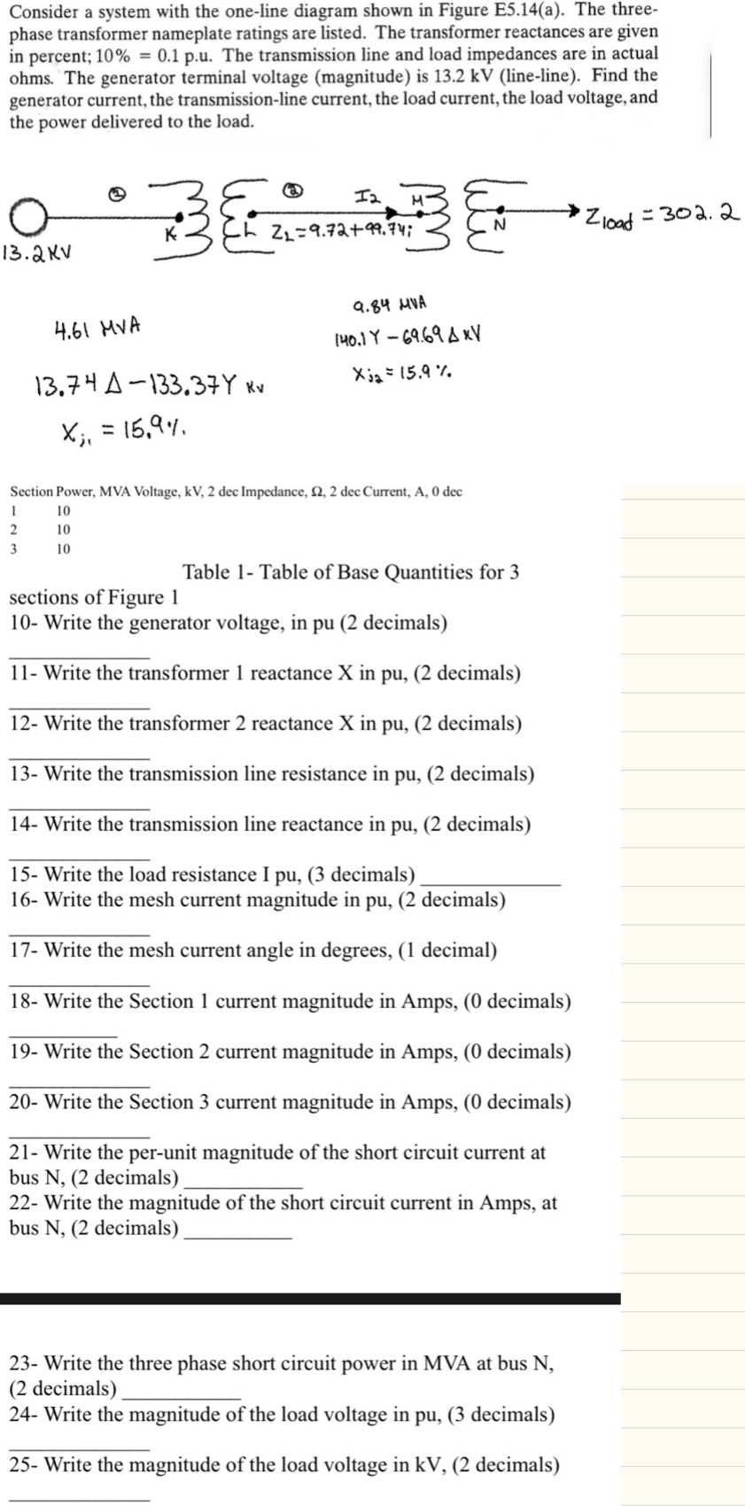
Consider a system with the oneline diagram shown in Figure Ea The threephase transformer nameplate ratings are listed. The transformer reactances are given in percent; The transmission line and load impedances are in actual ohms. The generator terminal voltage magnitude is kV lineline Find the
Section Power, MVA Voltage, kV dec Impedance, dec Current, dec
table
Table Table of Base Quantities for sections of Figure
Write the generator voltage, in pu decimals
Write the transformer reactance X in pu decimals
Write the transformer reactance X in pu decimals
Write the transmission line resistance in pu decimals
Write the transmission line reactance in pu decimals
Write the load resistance I pu decimals
Write the mesh current magnitude in pu decimals
Write the mesh current angle in degrees, decimal
Write the Section current magnitude in Amps, decimals
Write the perunit magnitude of the short circuit current at bus N decimals
Write the magnitude of the short circuit current in Amps, at bus N decimals
Write the three phase short circuit power in MVA at bus N decimals
Write the magnitude of the load voltage in pu decimals
Step by Step Solution
There are 3 Steps involved in it
1 Expert Approved Answer
Step: 1 Unlock

Question Has Been Solved by an Expert!
Get step-by-step solutions from verified subject matter experts
Step: 2 Unlock
Step: 3 Unlock