

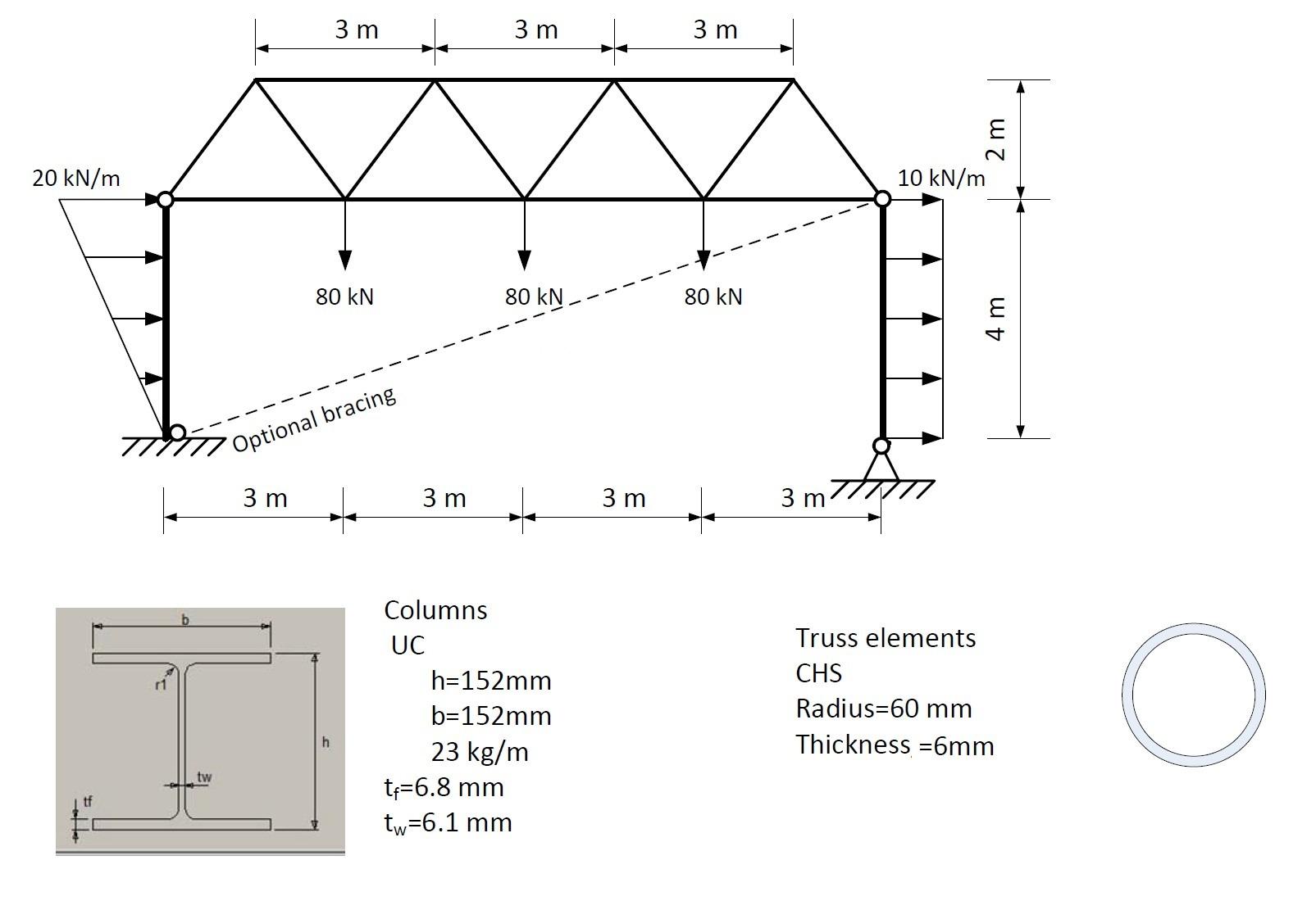
Question: Consider Figure 1 which shows a truss structure supported by two columns. A bracing component with a stiffness k = 2 . 6 MN /
Consider Figure which shows a truss structure supported by two columns. A bracing component with a stiffness k MNm is also supplied as shown. The loadings applied to the structure are also shown in the figure. Use the following information to model this problem and to answer the questions below.
Use single bar elements to model the truss.
Use EulerBernoulli beam elements of mm length with the standard cubic formulation to model the columns.
The sections of the components are shown in Figure
The material is structural steel with E GPa,
u kgm and yield stress of MPa.
The supports at the bottom of the columns are fixed on the left and pinned on the right.
The connections between the columns and the truss and the bracing component are hinged as shown.
The structure is laterally supported for outofplane displacement.
Ignore the own weight of the bracing component.
Answer the following:
Sketch a schematization of the problem for modelling in Abaqus. The schematization must show clear annotations where the following are described:
Boundary conditions clearly indicate which degrees of freedom are clamped.
Loading and how it is applied.
Material properties.
The number sketch the nodes and type of finite elements that are used give the Abaqus element name
Model the structure using Abaqus and then analyse the model to determine the effect of the loading, including the own weight. Use hand sketches with proper annotations to show all important values maxima and minima points, the position of inflection points, etc. Note that you must use the Abaqus print option to show the deformed shape, bending moment diagrams etc. Show diagrams for the following:
a Reaction forces together with the resulting deflected shape of the structure. Also, make note of the magnitude in mm and position of the maximum horizontal and vertical deflections.
b The axial force diagram of all the components.
c The bending moment diagrams for the columns.
d The shear force diagrams for the columns.
Check the members of the truss structure for yielding in compression or tension. The maximum stress allowed fy for tension and compression members.
Suppose the bracing element is removed. Modify the model of the structure and determine the displaced shape of the structure. Also, make note of the magnitude in mm and position of the maximum horizontal and vertical deflections.
Step by Step Solution
There are 3 Steps involved in it
1 Expert Approved Answer
Step: 1 Unlock

Question Has Been Solved by an Expert!
Get step-by-step solutions from verified subject matter experts
Step: 2 Unlock
Step: 3 Unlock