

Question: Consider the 4 - node network shown in figure Q 4 . Generator ( mathbf { G 1 } ) is connected
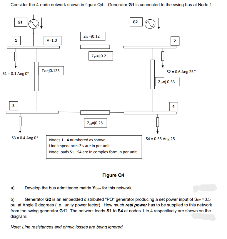
Consider the node network shown in figure Q Generator mathbfG is connected to the swing bus at Node
Figure Q
a Develop the bus admittance matrix Ytext bus for this network.
b Generator mathbfG is an embedded distributed PQ generator producing a set power input of mathrmSmathrmG pu at Angle degrees ie unity power factor How much real power has to be supplied to this network from the swing generator G The network loads mathbfS to mathbfS at nodes to respectively are shown on the diagram.
Note: Line resistances and ohmic losses are being ignored.
Step by Step Solution
There are 3 Steps involved in it
1 Expert Approved Answer
Step: 1 Unlock

Question Has Been Solved by an Expert!
Get step-by-step solutions from verified subject matter experts
Step: 2 Unlock
Step: 3 Unlock