

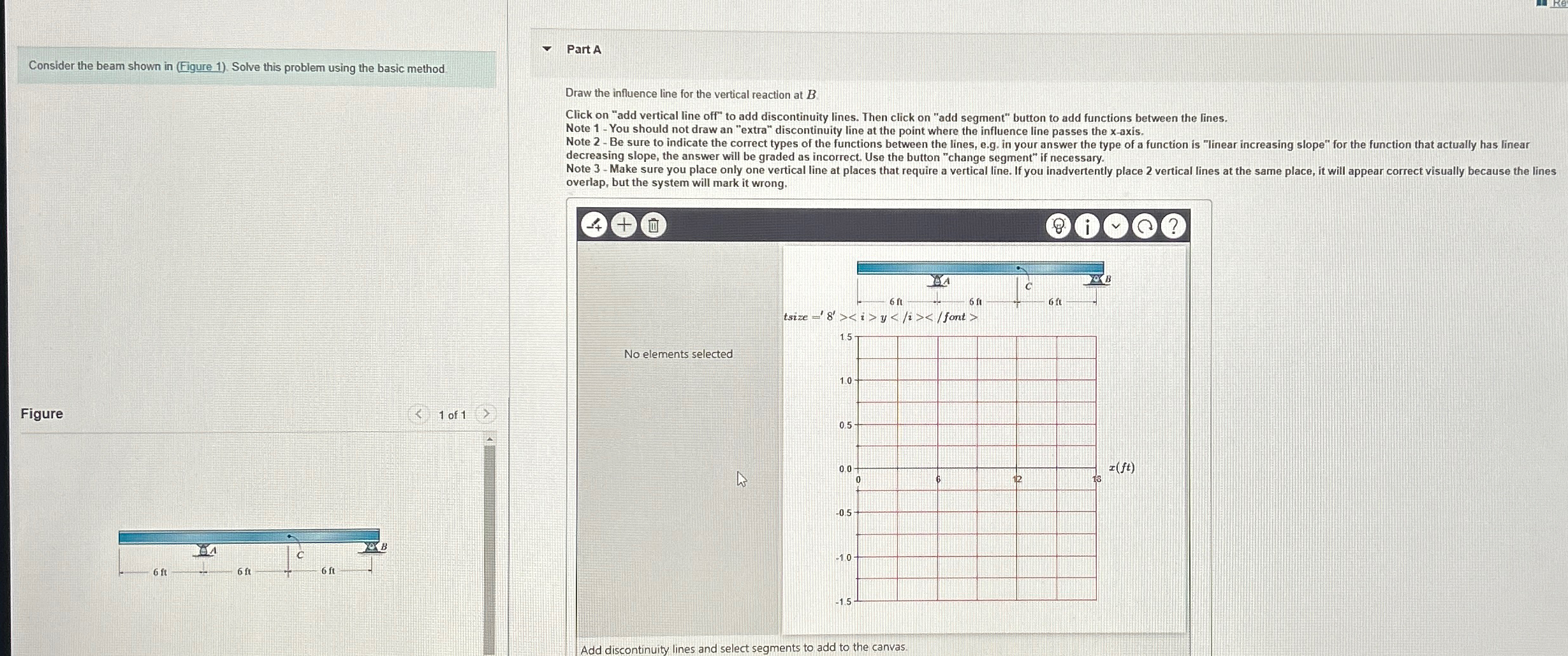
Question: Consider the beam shown in ( Figure 1 ) . Solve this problem using the basic method Figure Part A Draw the influence line for
Consider the beam shown in Figure Solve this problem using the basic method
Figure
Part A
Draw the influence line for the vertical reaction at
Click on "add vertical line off" to add discontinuity lines. Then click on "add segment" button to add functions between the lines.
Note You should not draw an "extra" discontinuity line at the point where the influence line passes the axis.
Note Be sure to indicate the correct types of the functions between the lines, eg in your answer the type of a function is "linear increasing slope" for the function that actually has linear decreasing slope, the answer will be graded as incorrect. Use the button "change segment" if necessary.
Note Make sure you place only one vertical line at places that require a vertical line. If you inadvertently place vertical lines at the same place, it will appear correct visually because the lines overlap, but the system will mark it wrong.
Add discontinuity lines and select
segments to add to the canvas.
Please draw the influence line for shear just to the right lf the rocker at A and the influence line for the bending moment at C
Step by Step Solution
There are 3 Steps involved in it
1 Expert Approved Answer
Step: 1 Unlock

Question Has Been Solved by an Expert!
Get step-by-step solutions from verified subject matter experts
Step: 2 Unlock
Step: 3 Unlock