

Question: Consider the circuit and its code shown in Figure Q5. Solve the following questions. a. Use your knowledge of programming and devices design, briefly describe
Consider the circuit and its code shown in Figure Q5. Solve the following questions. a. Use your knowledge of programming and devices design, briefly describe the INTENDED purpose of the circuit. b. When simulated, the device is not behaving right. (1) Analyze what is wrong with the circuit? (2) Provide a simple solution to the problem.
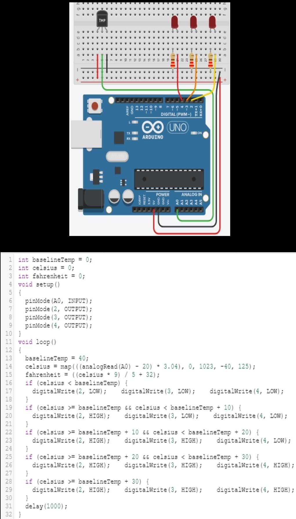
Figure Q5
TMP 10 ... ... 12 ... O con DIGITAL (PWM-) O UNO TX TON RX ARDUINO POWER ANALOG IN ! 1 int baselineTemp = 0; 2 int celsius = 0; 3 int fahrenheit = 0; 4 void setup() 5 { 6 pinMode (AO, INPUT); 7 pinMode (2, OUTPUT); 8 pinMode (3, OUTPUT); 9 pinMode(4, OUTPUT); 10 ) 11 void loop() 12 { 13 baselineTemp = 40; 14 celsius = map(((analogRead(AO) - 20) - 3.04), 0, 1023, -40, 125); 15 fahrenheit = ((celsius - 9) / 5 + 32); 16 if (celsius = baseline Temp && celsius = baselineTemp + 10 && celsius = baselineTemp + 20 && celsius = baseline Temp + 30) { 29 digitalWrite (2, HIGH); digitalWrite(3, HIGH); digitalWrite(4, HIGH); 30 } 31 delay(1000); 32 }
Step by Step Solution
There are 3 Steps involved in it

Get step-by-step solutions from verified subject matter experts