

Question: Consider the circuit shown in Figure 6 . It uses a three - bit wide 5 - to - 1 multiplexer to enable the selection
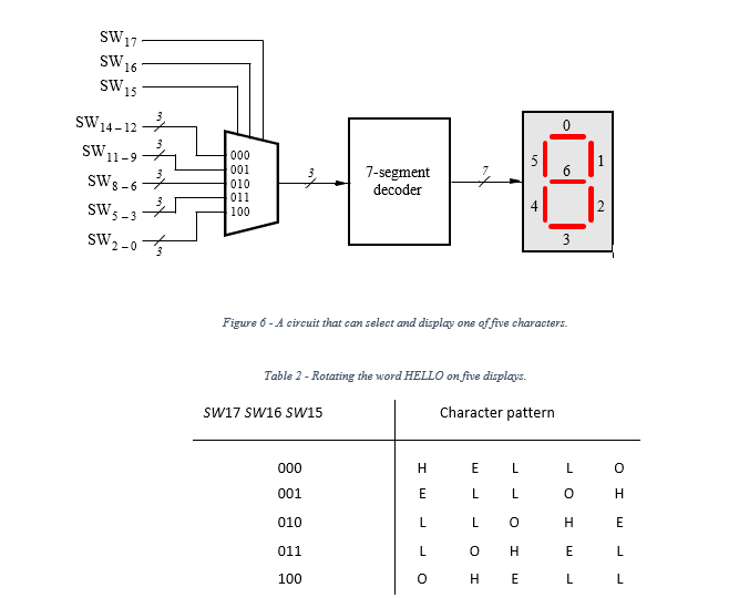
Consider the circuit shown in Figure It uses a threebit wide to multiplexer to enable the selection of five characters that are displayed on a segment display. Using the segment decoder from Part IV this circuit can display any of the characters H E L O and blank The character codes are set according to Table by using the switches SW and a specific character is selected for display by setting the switches SW
Use the circuits from Parts III and IV as subcircuits in this entity. The purpose of your circuit is to display the word HELLO on the five displays that is composed of the characters in Table and be able to rotate this word in a circular fashion across the displays when the switches SW are toggled. The circuit should produce the output patterns illustrated in Table
Consider the circuit shown in Figure It uses a threebit wide to multiplexer to enable the selection of five characters that are displayed on a segment display. Using the segment decoder from Part IV this circuit can display any of the characters H E L O and blank The character codes are set according to Table by using the switches SW and a specific character is selected for display by setting the switches SW
Use the circuits from Parts III and IV as subcircuits in this entity. The purpose of your circuit is to display the word HELLO on the five displays that is composed of the characters in Table and be able to rotate this word in a circular fashion across the displays when the switches SW are toggled. The circuit should produce the output patterns illustrated in Table Consider the circuit shown in Figure It uses a threebit wide to multiplexer to enable the selection of five characters that are displayed on a segment display. Using the segment decoder from Part IV this circuit can display any of the characters H E L O and blank The character codes are set according to Table by using the switches SW and a specific character is selected for display by setting the switches SW
Use the circuits from Parts III and IV as subcircuits in this entity. The purpose of your circuit is to display the word HELLO on the five displays that is composed of the characters in Table and be able to rotate this word in a circular fashion across the displays when the switches SW are toggled. The circuit should produce the output patterns illustrated in Table Consider the circuit shown in Figure It uses a threebit wide to multiplexer to enable the selection of five characters that are displayed on a segment display. Using the segment decoder from Part IV this circuit can display any of the characters H E L O and blank The character codes are set according to Table by using the switches SW and a specific character is selected for display by setting the switches SW
Use the circuits from Parts III and IV as subcircuits in this entity. The purpose of your circuit is to display the word HELLO on the five displays that is composed of the characters in Table and be able to rotate this word in a circular fashion across the displays when the switches SW are toggled. The circuit should produce the output patterns illustrated in Table
I need the full design of the circuit shown in the picture.
Step by Step Solution
There are 3 Steps involved in it
1 Expert Approved Answer
Step: 1 Unlock

To design the circuit for displaying and rotating the word HELLO on 7segment displays following the ... View full answer
Question Has Been Solved by an Expert!
Get step-by-step solutions from verified subject matter experts
Step: 2 Unlock
Step: 3 Unlock