

Question: Consider the digital circuit given in the below figure where S1, S2, and S3 are SPDT switches; U1, U2, and U3 are inverters; U4, U5,
Consider the digital circuit given in the below figure where S1, S2, and S3 are SPDT switches; U1, U2, and U3 are inverters; U4, U5, U6, and U7 are three-input AND gates; U8, U9, and U10 are two-input AND gates; U11 is a four-input OR gate, and U12 is a three-input OR gate. 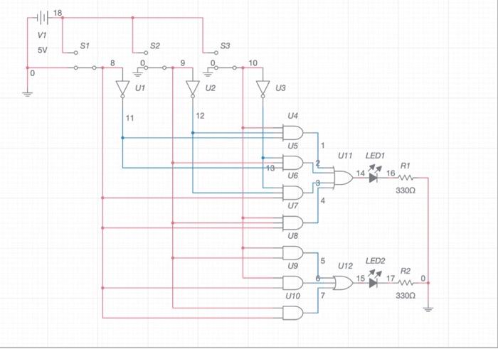
Construct the circuit, and obtain the ON/OFF states of the LEDs for all combinations of the switches by completing Table 1. Note that a switch is assumed to be in state 1 when connected to the 5V supply and in state 0 when connected to the ground.
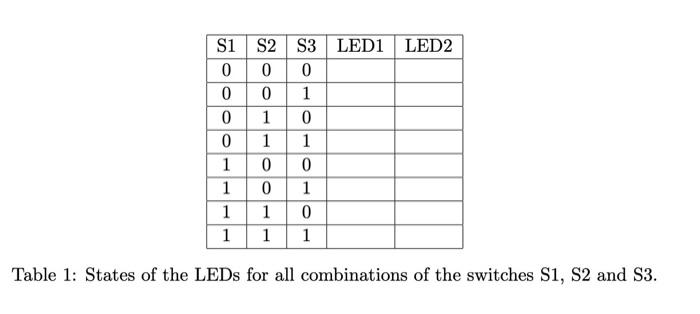
Hlll 18 S V1 5V S1 S2 S3 8 9 10 0 She U1 U2 U3 11 12 14 U5 1 U11 LED1 19 R1 U6 14 16 33002 4 U7 U8 5 U9 LED2 U12 R2 15 17 w 3300 0 U10 7 S1 S2 S3 LED1 LED2 0 0 0 00 1 0 1 0 0 1 1 1 0 0 1 0 1 1 1 0 1 1 1 Table 1: States of the LEDs for all combinations of the switches S1, S2 and S3
Step by Step Solution
There are 3 Steps involved in it
1 Expert Approved Answer
Step: 1 Unlock

Question Has Been Solved by an Expert!
Get step-by-step solutions from verified subject matter experts
Step: 2 Unlock
Step: 3 Unlock