

Question: Consider the following behavior of a sequential logic. A state machine for this behavior has one input named X, one output named Z, and
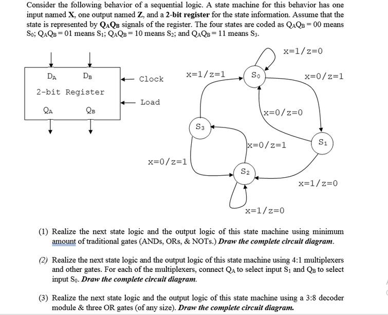
Consider the following behavior of a sequential logic. A state machine for this behavior has one input named X, one output named Z, and a 2-bit register for the state information. Assume that the state is represented by QAQB signals of the register. The four states are coded as QAQB = 00 means So; QAQB 01 means Si; QAQB 10 means S2; and QAQB = 11 means S3. x=1/z=1 So DA DB Clock 2-bit Register Load QA QB x=1/2=0 x=0/z=1 x=0/z=0 S3 S1 x=0/z=1 x=0/z=1 S2 x=1/z=0 x=1/z=0 (1) Realize the next state logic and the output logic of this state machine using minimum amount of traditional gates (ANDS, ORS, & NOTs.) Draw the complete circuit diagram. (2) Realize the next state logic and the output logic of this state machine using 4:1 multiplexers and other gates. For each of the multiplexers, connect QA to select input S and QB to select input So. Draw the complete circuit diagram. (3) Realize the next state logic and the output logic of this state machine using a 3:8 decoder module & three OR gates (of any size). Draw the complete circuit diagram.
Step by Step Solution
There are 3 Steps involved in it

Get step-by-step solutions from verified subject matter experts