

Question: consider the following state graph : This state graph can be implemented with fsm_test module. module fsm_test( output states_t st, input logic [1:0] in, input
consider the following state graph :
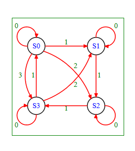
This state graph can be implemented with fsm_test module.
module fsm_test( output states_t st, input logic [1:0] in, input logic clk, reset ); always_ff @(posedge clk) begin if ( reset ) stComplete the test_gen module,
module test_gen(output logic clk, reset, output logic [1:0] out );which provides a test bench, for the fsm_test, to cause the finite state machine to traverse the following states.
S0, S1, S2, S3, S1, S2, S2, S3, S0, S3The provided test bench code already starts at S0, and advances to S1 :
module test_gen(output logic clk, reset, output logic [1:0] out );
task clock_cycle(integer n); repeat( n ) begin clk = 0; #5; clk = 1; #5; clk = 0; end endtask
initial begin out = 0; reset = 1; clock_cycle(1); reset = 0; // S0 out = 1; clock_cycle(1); // S1
// complete the rest end endmodule
0 0 1 SO S1 2 3 1 1 1 S3 S2 0 0
Step by Step Solution
There are 3 Steps involved in it
1 Expert Approved Answer
Step: 1 Unlock

Question Has Been Solved by an Expert!
Get step-by-step solutions from verified subject matter experts
Step: 2 Unlock
Step: 3 Unlock