

Question: 1. Build the circuit model for full-wave diode rectifier in PSpice as shown in Fig. 4. The value of the load resistor is 10
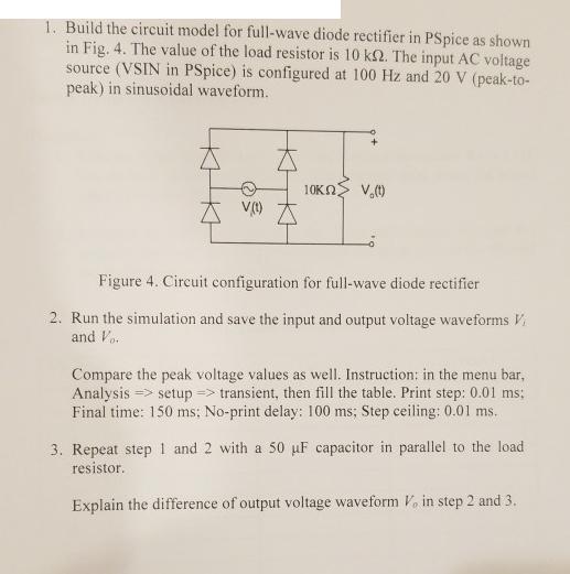
1. Build the circuit model for full-wave diode rectifier in PSpice as shown in Fig. 4. The value of the load resistor is 10 k2. The input AC voltage source (VSIN in PSpice) is configured at 100 Hz and 20 V (peak-to- peak) in sinusoidal waveform. V(t) IKKH 10KM V.() Figure 4. Circuit configuration for full-wave diode rectifier 2. Run the simulation and save the input and output voltage waveforms V and Vo. Compare the peak voltage values as well. Instruction: in the menu bar, Analysis => setup => transient, then fill the table. Print step: 0.01 ms; Final time: 150 ms; No-print delay: 100 ms; Step ceiling: 0.01 ms. 3. Repeat step 1 and 2 with a 50 uF capacitor in parallel to the load resistor. Explain the difference of output voltage waveform V. in step 2 and 3.
Step by Step Solution
There are 3 Steps involved in it

Get step-by-step solutions from verified subject matter experts