

Question: Consider the linear feedback shift register illustrated in Figure 1 which consists of a five-stage register for storage and shifting, a modulo-2 adder, and
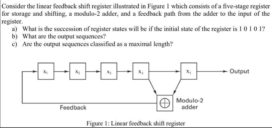
Consider the linear feedback shift register illustrated in Figure 1 which consists of a five-stage register for storage and shifting, a modulo-2 adder, and a feedback path from the adder to the input of the register. a) What is the succession of register states will be if the initial state of the register is 1 0 1 0 1? b) What are the output sequences? c) Are the output sequences classified as a maximal length? XI H X Feedback X3 X4 X; Modulo-2 adder Figure 1: Linear feedback shift register Output
Step by Step Solution
3.37 Rating (144 Votes )
There are 3 Steps involved in it
a The new state after the first shift is 11010 b The output sequence afte... View full answer

Get step-by-step solutions from verified subject matter experts