

Question: Consider the MIPS store word instruction as implemented on the datapath above (Figure 4.2 from textbook): swR4, -12(R3)//Memory[ Reg[3] + signextended(-12) ] Circle the correct
Consider the MIPS store word instruction as implemented on the datapath above (Figure 4.2 from textbook):
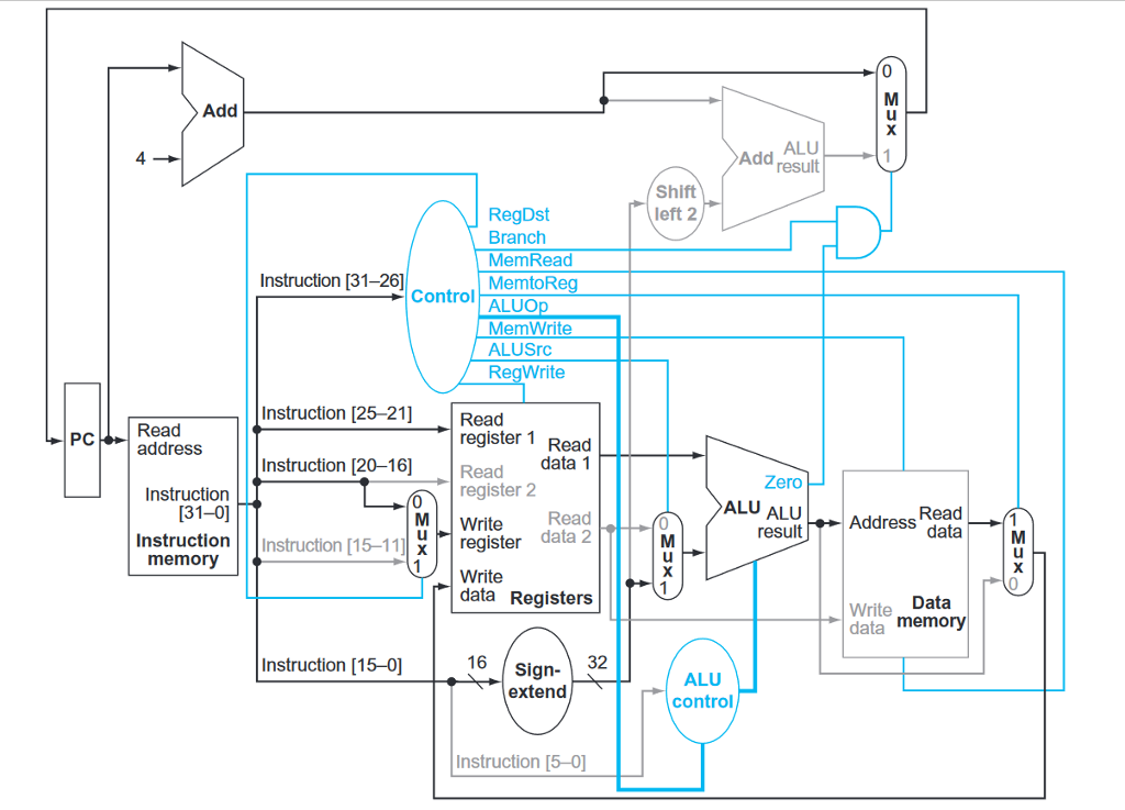
swR4, -12(R3)//Memory[ Reg[3] + signextended(-12) ]
Circle the correct value 0 or 1 for the control signals (a-d) and circle whether each of the three muxes (e-g) selects its upper input, lower input, or don't care. For the ALU operation (h) circle one of the function names. (The Zero condition signal will be assumed to be 0.)
Branch = 0 1 (e) Mux1 (upper left; output to PC) = upper, lower, don't care
MemRead = 0 1 (f) Mux2 (upper middle; output to Data port of Regs) = upper, lower, don't care
MemWrite = 0 1 (g) Mux3 (lower middle; output to bottom leg of ALU) = upper, lower, don't care
RegWrite = 0 1 (h) ALU operation = and, or, add, subtract, set-on-less-than, nor
Add ALU Add result 4 Shift left 2 RegDst Branch MemRead MemtoR Instruction [31-26] Control ALUO MemWrite ALUSrC RegWrite Instruction [25-21] Read Read address register 1 Read Instruction [20-16 Readdata 1 PC Zero ALU ALU result Instruction register 2 [31-0] Write Read data 2 0 Address Read InstructionInstruction [15-11 X regist U I write memory data Registers Write Data data memory 16 Sign- extend Instruction [15-0] 32 ALU control Instruction [5-0] Add ALU Add result 4 Shift left 2 RegDst Branch MemRead MemtoR Instruction [31-26] Control ALUO MemWrite ALUSrC RegWrite Instruction [25-21] Read Read address register 1 Read Instruction [20-16 Readdata 1 PC Zero ALU ALU result Instruction register 2 [31-0] Write Read data 2 0 Address Read InstructionInstruction [15-11 X regist U I write memory data Registers Write Data data memory 16 Sign- extend Instruction [15-0] 32 ALU control Instruction [5-0]
Step by Step Solution
There are 3 Steps involved in it

Get step-by-step solutions from verified subject matter experts