

Question: Consider the pendulum shown in Figure 1, where & denotes the length of the rod and m denotes the mass of the bob. We
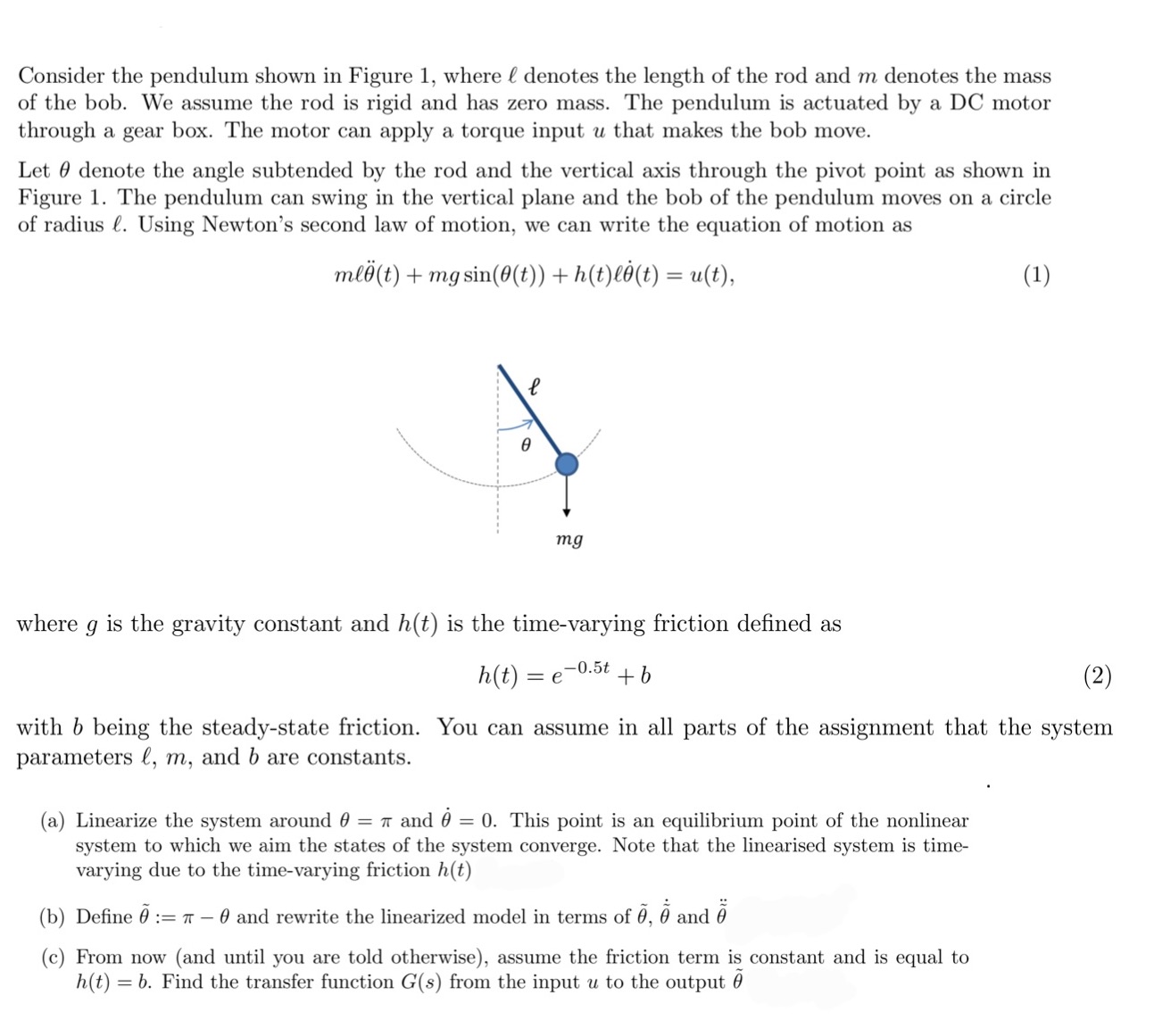
Consider the pendulum shown in Figure 1, where & denotes the length of the rod and m denotes the mass of the bob. We assume the rod is rigid and has zero mass. The pendulum is actuated by a DC motor through a gear box. The motor can apply a torque input u that makes the bob move. Let denote the angle subtended by the rod and the vertical axis through the pivot point as shown in Figure 1. The pendulum can swing in the vertical plane and the bob of the pendulum moves on a circle of radius . Using Newton's second law of motion, we can write the equation of motion as ml (t) + mg sin(0(t)) + h(t)l(t) = u(t), l 0 mg where 9 is the gravity constant and h(t) is the time-varying friction defined as h(t) = = e -0.5t +b (1) with b being the steady-state friction. You can assume in all parts of the assignment that the system parameters l, m, and b are constants. (a) Linearize the system around 0 = and = 0. This point is an equilibrium point of the nonlinear system to which we aim the states of the system converge. Note that the linearised system is time- varying due to the time-varying friction h(t) (b) Define 5 := 0 and rewrite the linearized model in terms of , I and (c) From now (and until you are told otherwise), assume the friction term is constant and is equal to h(t) = b. Find the transfer function G(s) from the input u to the output
Step by Step Solution
There are 3 Steps involved in it
The image contains a description of a pendulum system actuated by a DC motor along with its equation of motion and a graph depicting the pendulum its ... View full answer

Get step-by-step solutions from verified subject matter experts