

Question: Consider the per-unit impedance network diagram shown in Fig. 3. Node 0 is the reference node. Calculate the complex power supplied to the network
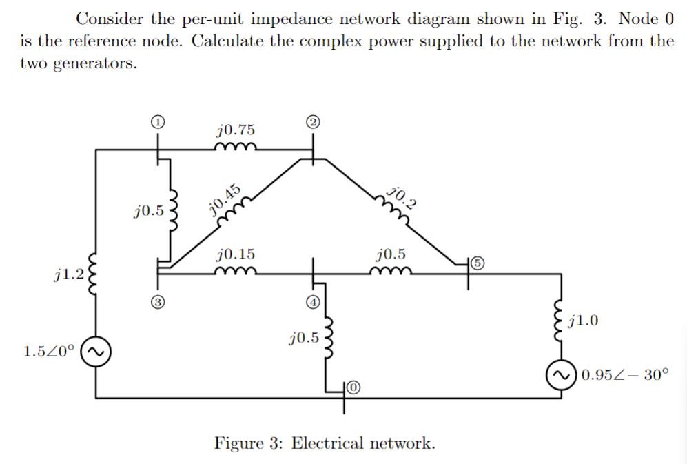
Consider the per-unit impedance network diagram shown in Fig. 3. Node 0 is the reference node. Calculate the complex power supplied to the network from the two generators. j1.2 1.520 (~ j0.5 j0.75 j0.45 j0.15 (4) j0.5 j0.2 j0.5 Figure 3: Electrical network. j1.0 ~0.952-30
Step by Step Solution
★★★★★
3.54 Rating (147 Votes )
There are 3 Steps involved in it
1 Expert Approved Answer
Step: 1 Unlock

SOLUTION The perunit impedance network diagram shown in Fig 3 consists of three generators and four loads connected through a series of transmission l... View full answer
Question Has Been Solved by an Expert!
Get step-by-step solutions from verified subject matter experts
Step: 2 Unlock
Step: 3 Unlock