

Question: Consider the register transfer statements given below (assume all registers are 4-bit): CIA C2: RI *-RI+ R3 (Addition) -CI C2: RI f RI - R2
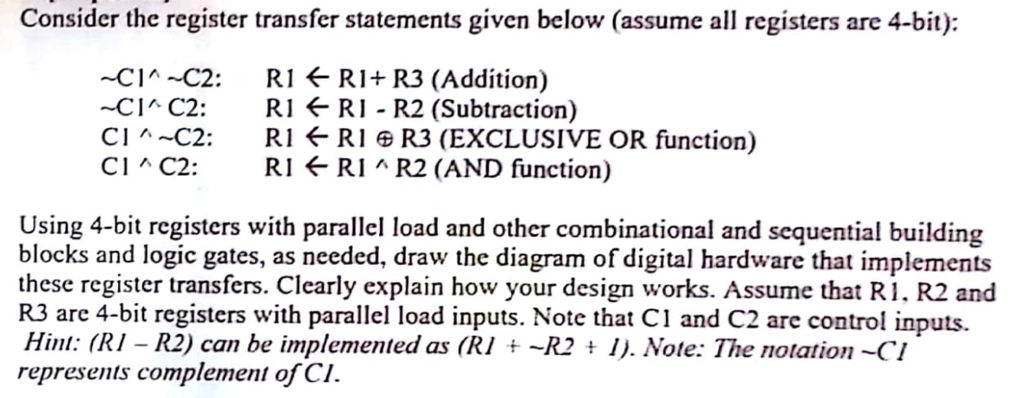
Consider the register transfer statements given below (assume all registers are 4-bit): CIA C2: RI *-RI+ R3 (Addition) -CI C2: RI f RI - R2 (Subtraction) Cl ^ ~C2: RI RIR3 (EXCLUSIVE OR function) Cl ^ C2: RI RI ^ R2 (AND function) Using 4-bit registers with parallel load and other combinational and sequential building blocks and logic gates, as needed, draw the diagram of digital hardware that implements these register transfers. Clearly explain how your design works. Assume that R1. R2 and R3 are 4-bit registers with parallel load inputs. Note that CI and C2 are control inputs. Hint: (RI - R2) can be implemented as (RI t -R2I). Note: The notation-CI represents complement of CI. Consider the register transfer statements given below (assume all registers are 4-bit): CIA C2: RI *-RI+ R3 (Addition) -CI C2: RI f RI - R2 (Subtraction) Cl ^ ~C2: RI RIR3 (EXCLUSIVE OR function) Cl ^ C2: RI RI ^ R2 (AND function) Using 4-bit registers with parallel load and other combinational and sequential building blocks and logic gates, as needed, draw the diagram of digital hardware that implements these register transfers. Clearly explain how your design works. Assume that R1. R2 and R3 are 4-bit registers with parallel load inputs. Note that CI and C2 are control inputs. Hint: (RI - R2) can be implemented as (RI t -R2I). Note: The notation-CI represents complement of CI
Step by Step Solution
There are 3 Steps involved in it

Get step-by-step solutions from verified subject matter experts