

Question: Consider the shown circuit, where ( mathrm { R } = 5 0 0 Omega , mathrm { ~L } =
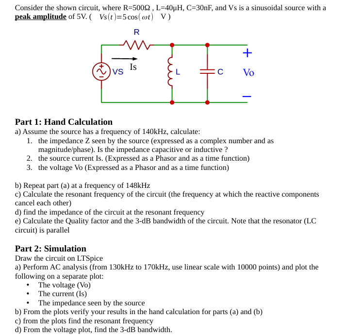
Consider the shown circuit, where mathrmROmegamathrm~Lmu mathrmHmathrmCmathrmnF and Vs is a sinusoidal source with a peak amplitude of mathrm~Vquad V stcos omega tquad mathrmV
Part : Hand Calculation
a Assume the source has a frequency of kHz calculate:
the impedance Z seen by the source expressed as a complex number and as magnitudephase Is the impedance capacitive or inductive
the source current IsExpressed as a Phasor and as a time function
the voltage Vo Expressed as a Phasor and as a time function
b Repeat part a at a frequency of kHz
c Calculate the resonant frequency of the circuit the frequency at which the reactive components cancel each other
d find the impedance of the circuit at the resonant frequency
e Calculate the Quality factor and the dB bandwidth of the circuit. Note that the resonator LC circuit is parallel
Part : Simulation
Draw the circuit on LTSpice
a Perform AC analysis from kHz to kHz use linear scale with points and plot the following on a separate plot:
The voltage Vo
The current Is
The impedance seen by the source
b From the plots verify your results in the hand calculation for parts a and b
c from the plots find the resonant frequency
d From the voltage plot, find the dB bandwidth.
Step by Step Solution
There are 3 Steps involved in it
1 Expert Approved Answer
Step: 1 Unlock

Question Has Been Solved by an Expert!
Get step-by-step solutions from verified subject matter experts
Step: 2 Unlock
Step: 3 Unlock