

Question: Consider the structural problem shown in Figure 4.1a y X L N Figure 4.1a The slab of linearly elastic material is subjected to shear
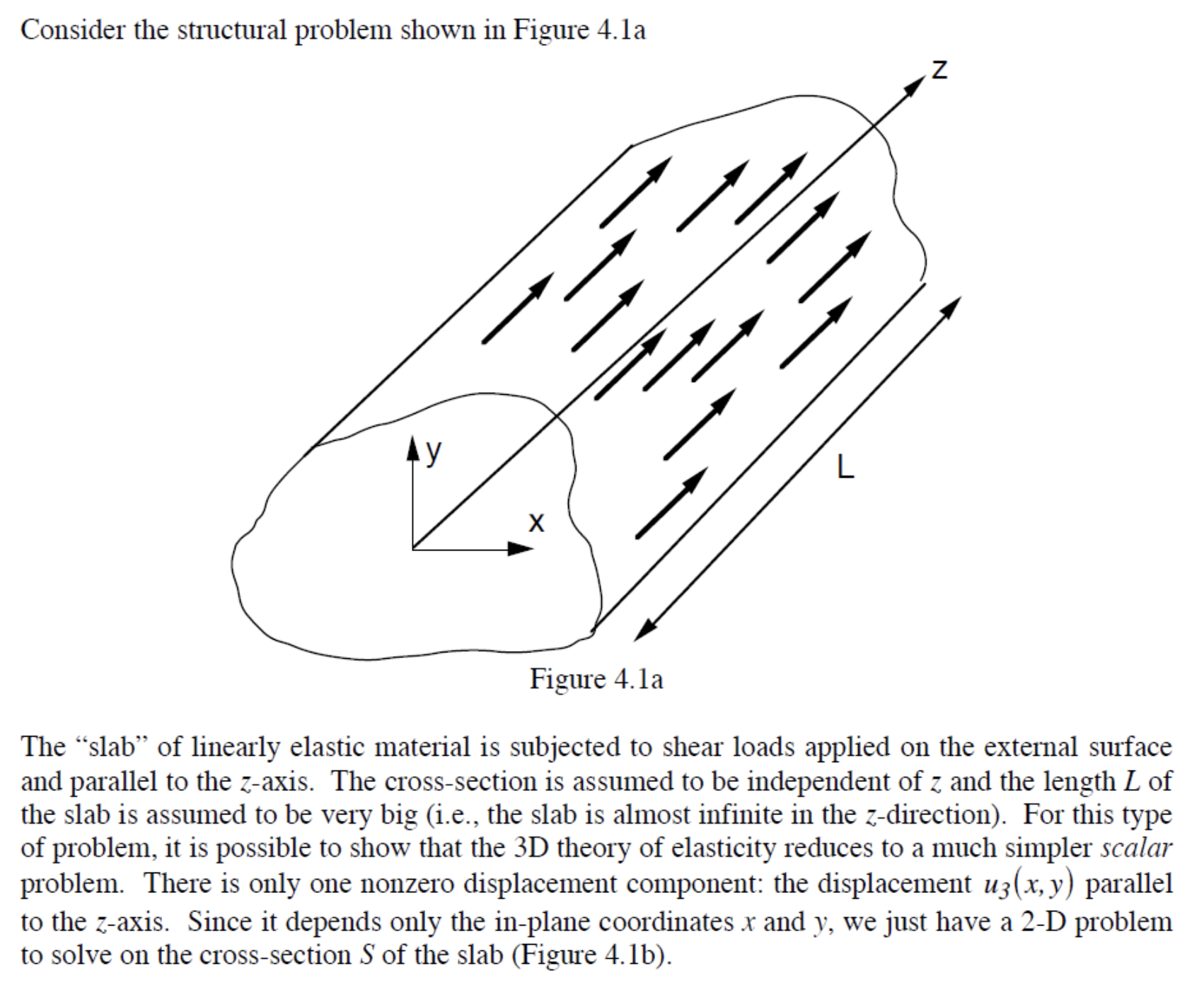
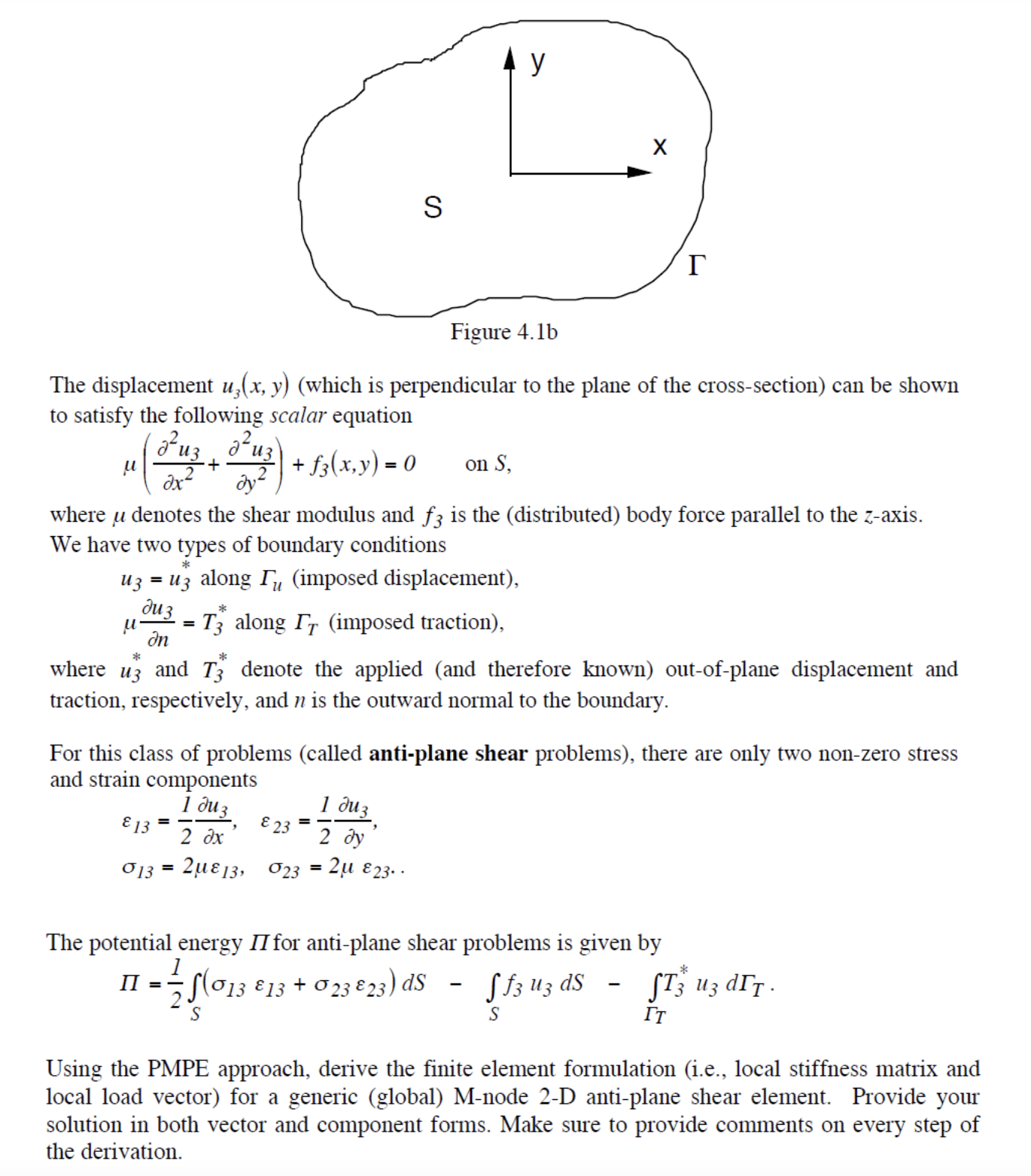
Consider the structural problem shown in Figure 4.1a y X L N Figure 4.1a The "slab" of linearly elastic material is subjected to shear loads applied on the external surface and parallel to the z-axis. The cross-section is assumed to be independent of z and the length L of the slab is assumed to be very big (i.e., the slab is almost infinite in the z-direction). For this type of problem, it is possible to show that the 3D theory of elasticity reduces to a much simpler scalar problem. There is only one nonzero displacement component: the displacement u3(x, y) parallel to the z-axis. Since it depends only the in-plane coordinates x and y, we just have a 2-D problem to solve on the cross-section S of the slab (Figure 4.1b). u Figure 4.1b The displacement u(x, y) (which is perpendicular to the plane of the cross-section) can be shown to satisfy the following scalar equation Fuz dx 13 * uz = uz along Tu (imposed displacement), Juz In 013 + dy where u denotes the shear modulus and f3 is the (distributed) body force parallel to the z-axis. We have two types of boundary conditions = d uz\ = * + f3(x,y)= 0 on S, II = S * where u3 and T3 denote the applied (and therefore known) out-of-plane displacement and traction, respectively, and n is the outward normal to the boundary. = T3 along IT (imposed traction), For this class of problems (called anti-plane shear problems), there are only two non-zero stress and strain components 1 2 dx 213, 023 23 = y 1 duz 2 dy X 2 23.. r The potential energy II for anti-plane shear problems is given by - 75 (013 13 + 023 23) dS Sf3 uz ds S S - * ST3 uz dIT. IT Using the PMPE approach, derive the finite element formulation (i.e., local stiffness matrix and local load vector) for a generic (global) M-node 2-D anti-plane shear element. Provide your solution in both vector and component forms. Make sure to provide comments on every step of the derivation.
Step by Step Solution
3.37 Rating (150 Votes )
There are 3 Steps involved in it
Solutions Step 1 Step 1 Displacement field approximation Explanation Assuming a generic Mnode 2D ant... View full answer

Get step-by-step solutions from verified subject matter experts