

Question: Consider the truss below, secured at the nodes via clevis joints. (a) Sketch a FBD for elements AC, CE, BD, and the Clevis Pin
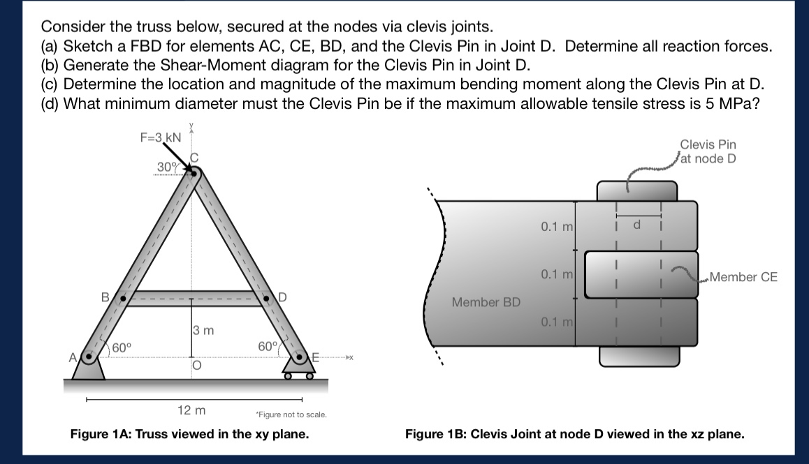
Consider the truss below, secured at the nodes via clevis joints. (a) Sketch a FBD for elements AC, CE, BD, and the Clevis Pin in Joint D. Determine all reaction forces. (b) Generate the Shear-Moment diagram for the Clevis Pin in Joint D. (c) Determine the location and magnitude of the maximum bending moment along the Clevis Pin at D. (d) What minimum diameter must the Clevis Pin be if the maximum allowable tensile stress is 5 MPa? F=3 KN 30% Clevis Pin at node D B D 3 m 60 60 F O 12 m *Figure not to scale. Figure 1A: Truss viewed in the xy plane. 0.1 m 0.1 m Member CE Member BD 0.1 m Figure 1B: Clevis Joint at node D viewed in the xz plane.
Step by Step Solution
There are 3 Steps involved in it

Get step-by-step solutions from verified subject matter experts