

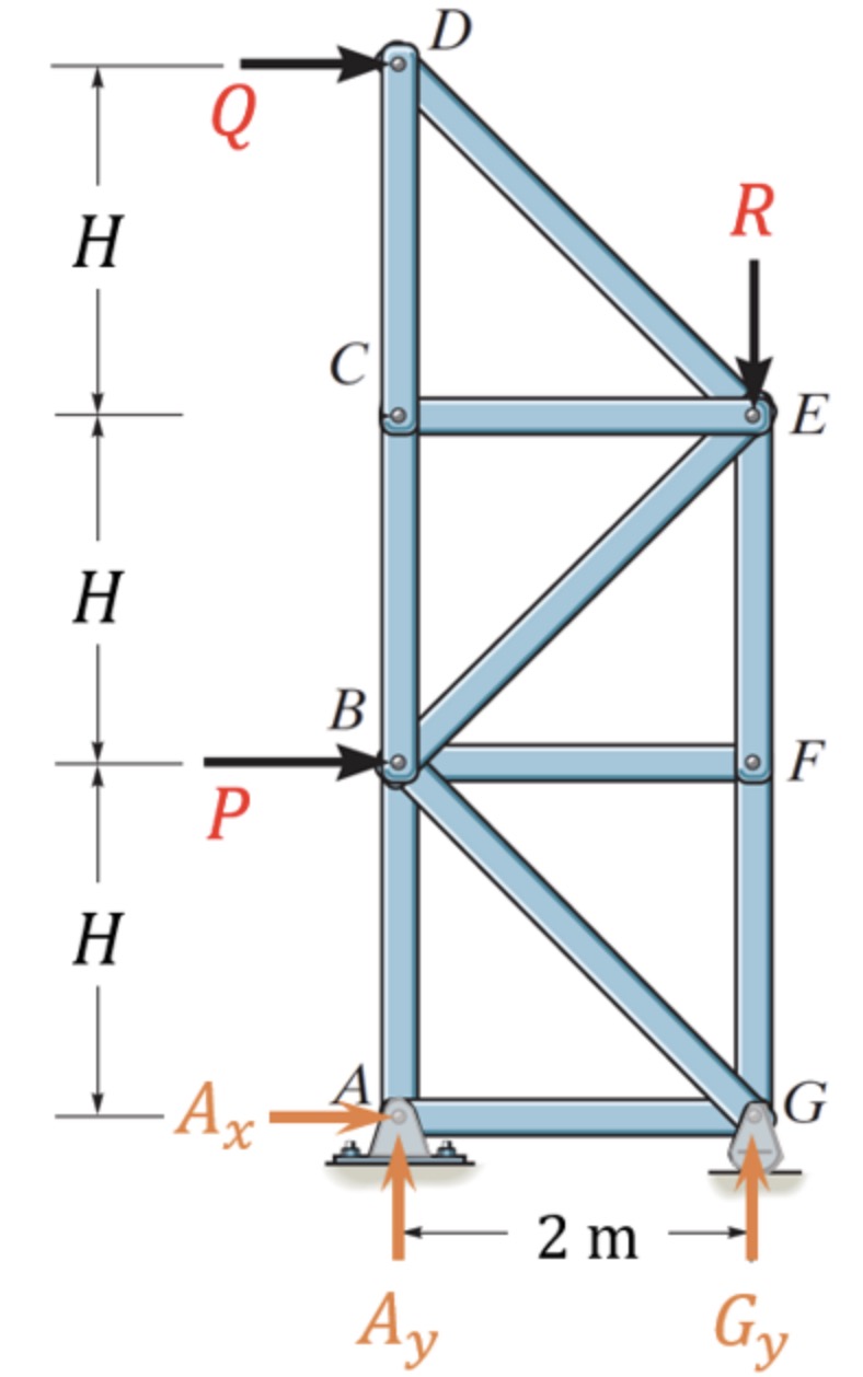
Question: Consider the truss in Figure P 4 , which is supported on a pin at point A and a rocker / roller at point G
Consider the truss in Figure P which is supported on a pin at point A and a rockerroller at point G It is loaded with two horizontal forces P kN and Q kN and a vertical force R kN The support reaction forces and their assumed directions are illustrated in the figure and their values are Ax kN Ay kN and Gy kN Here, H m
a Determine the force in member BE using the method of sections. Use a positive value to indicate tension and a negative value to indicate compression. Provide your answer in kN to decimal places. mark
Force in member BE kN
b Determine the force in member BC using the method of sections. Use a positive value to indicate tension and a negative value to indicate compression. Provide your answer in kN to decimal places. marks
Force in member BC kN
c Determine the force in member FE using the method of sections. Use a positive value to indicate tension and a negative value to indicate compression. Provide your answer in kN to decimal places. marks
Force in member FE kN
d Consider the case where the vertical load R remains pointing downwards but its magnitude can change. All other loads P and Q are unchanged. Determine the maximum allowable magnitude of R if support G only manages a force of kN upwards. Provide your answer in kN to decimal places. marks
Maximum allowable magnitude of R kN
Step by Step Solution
There are 3 Steps involved in it
1 Expert Approved Answer
Step: 1 Unlock

Question Has Been Solved by an Expert!
Get step-by-step solutions from verified subject matter experts
Step: 2 Unlock
Step: 3 Unlock