

Question: Construct the ladder logic diagram ( LD ) for the operation of the parking gate system illustrated in Figure P 1 Figure P 1 When
Construct the ladder logic diagram LD for the operation of the parking gate system illustrated in Figure P
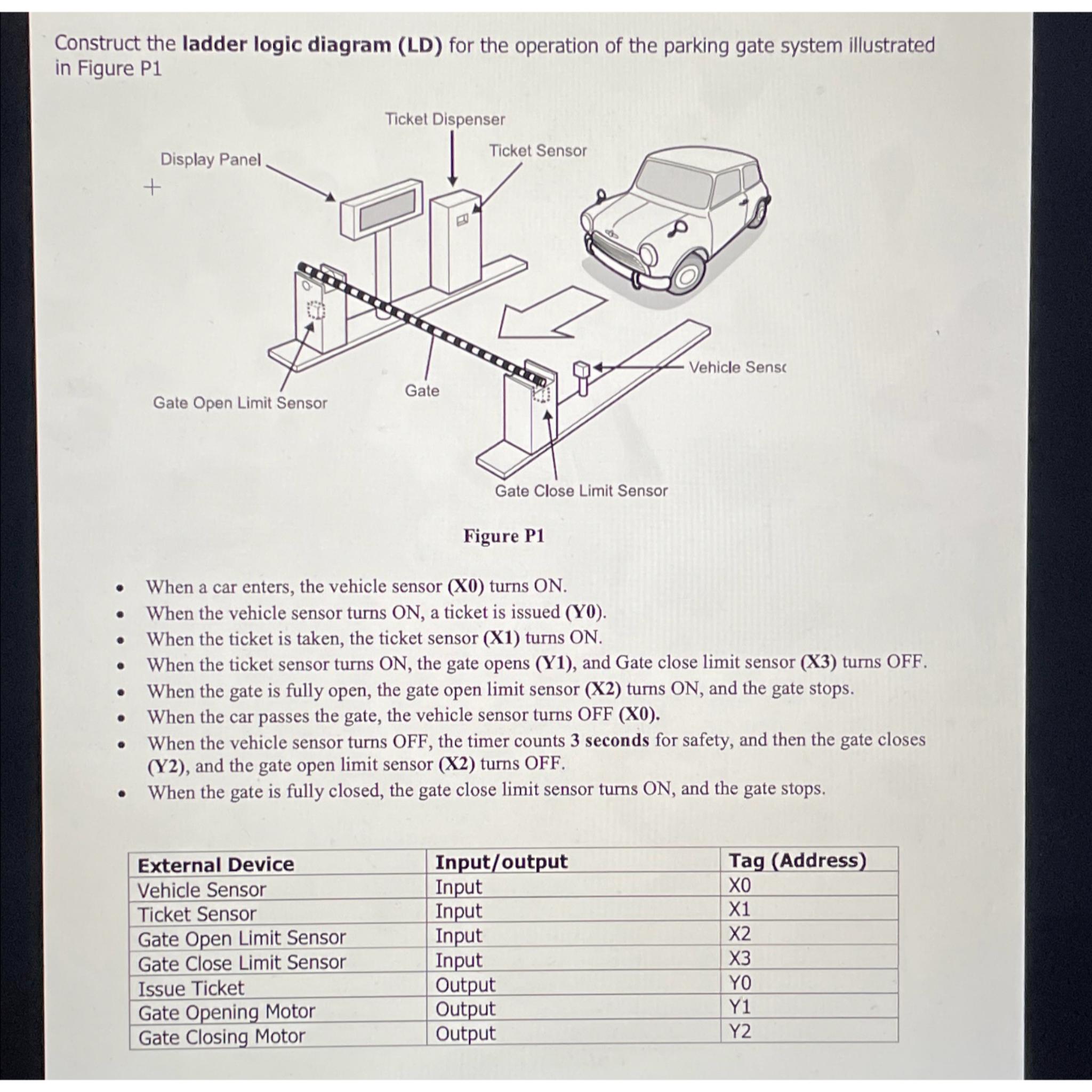
Figure P
When a car enters, the vehicle sensor turns
When the vehicle sensor turns a ticket is issued Y
When the ticket is taken, the ticket sensor X turns ON
When the ticket sensor turns ON the gate opens Y and Gate close limit sensor X turns OFF.
When the gate is fully open, the gate open limit sensor X turns ON and the gate stops.
When the car passes the gate, the vehicle sensor turns OFF X
When the vehicle sensor turns OFF, the timer counts seconds for safety, and then the gate closes Y and the gate open limit sensor X turns OFF.
When the gate is fully closed, the gate close limit sensor turns ON and the gate stops.
tableExternal Device,InputoutputTag AddressVehicle Sensor,Input,XTicket Sensor,Input,XGate Open Limit Sensor,Input,XGate Close Limit Sensor,Input,XIssue Ticket,Output,YGate Opening Motor,Output,YGate Closing Motor,Output,Y
Step by Step Solution
There are 3 Steps involved in it
1 Expert Approved Answer
Step: 1 Unlock

Question Has Been Solved by an Expert!
Get step-by-step solutions from verified subject matter experts
Step: 2 Unlock
Step: 3 Unlock