

Question: correct Learning Goal: The method of virtual work can be applied to beams and frames. The displacement of a specific point on a beam caused
correct
Learning Goal:
The method of virtual work can be applied to beams and frames. The displacement of a specific point on a beam caused by external loading can be determined using the virtual work equation where is the external virtual unit load acting on the beam in the directions of the deflection, is the internal virtual moment in the beam, expressed as a function of and caused by the external virtual unit load, is the internal moment in the beam, expressed as a function of and caused by real loads, is the member's length, is the modulus of elasticity, and I is the moment of inertia of the beam's crosssectional area. The slope angle can also be determined using the method of virtual work. Instead of a unit load, a unit couple moment is applie at the desired point. Once corresponding internal real moments and virtual moments have been determined, as a function of then the virtual work equation can be used to find the tangential rotation.
To use the virtual work method, start by removing the real loads and place a unit load or unit couple moment at the desired location in the direction the displacement or rotation is to be determined. For example, to determine the downward deflection at due to the load in Figure apply a unit virtual force down at
Establish coordinates for each region of the beam or frame that has no discontinuity of real or virtual load. In the example, three regions are required because there are discontinuities at and With all the real loads temporarily removed and the virtual load or couple moment in place, calculate the internal moment or as a function of each coordinate. Next, determine the internal real moments caused only by the real loads, using the same coordinates established for calculating the virtual moments.
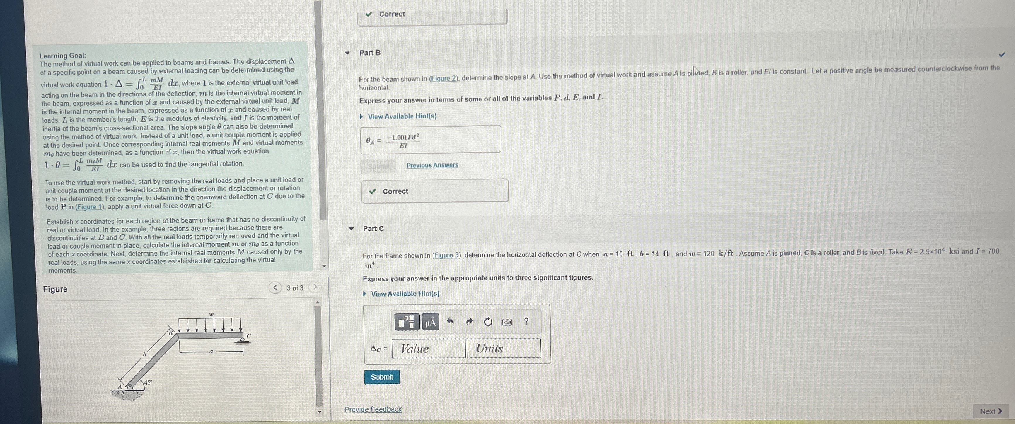
Figure
of
of
Part B
For the beam shown in Figure determine the slope at A Use the method of virtual work and assume is pilhted, is a roller, and I is constant. Let a positive angle be measured counterclockwise from the horizontal.
Express your answer in terms of some or all of the variables and I.
View Available Hints
Previous Answers
Correct
Part C
For the frame shown in Figure determine the horizontal deflection at when and Assume is pinned, is a roller, and is fixed. Take ksi and in
Express your answer in the appropriate units to three significant figures.
View Available Hints
Provide Feedback
Step by Step Solution
There are 3 Steps involved in it
1 Expert Approved Answer
Step: 1 Unlock

Question Has Been Solved by an Expert!
Get step-by-step solutions from verified subject matter experts
Step: 2 Unlock
Step: 3 Unlock