

Question: Could I please have the worked solution for the question as follows: a) Write down the linear difference equation describing the output, y(n)T, of the
Could I please have the worked solution for the question as follows:
a) Write down the linear difference equation describing the output, y(n)T, of the infinite impulse response filter shown below. 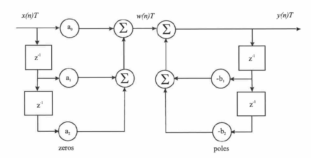
b) Draw a block diagram of the filter shown in part (a) in the direct form of layout i.e. with a single, final summation unit. What difficulty can arise in the practical realization of the filter in direct form when implemented with fixed point hardware.
c) Transform the linear difference equation you have derived in part (a) to obtain an expression for the pulse transfer function, G(z), of the filter.
d) Take the coefficients of the filter as a0=1, a1=1.5, a2=0.5, b1=0.2 and b2=0.08. Write down the resulting pulse transfer function G(z). Re-express the pulse transfer function as a product of terms and from this draw a block diagram of the filter in cascade form.
e) Now take the am coefficients of the filter as: a0 = 1, a1=a2=0 and leave the b1 and b2 coefficient values as in part (d). Re-write the resulting G(z) as the sum of two partial fractions and from this draw a block diagram of the filter in parallel form.
Step by Step Solution
There are 3 Steps involved in it

Get step-by-step solutions from verified subject matter experts