

Question: Create a code for a Simon game using python and a Tricket MO and a Piezoelectric Speaker. The game will have 4 buttons and 4
Create a code for a Simon game using python and a Tricket MO and a Piezoelectric Speaker. The game will have 4 buttons and 4 different color LEDs and a Piezo Speaker.
Send audio tones through the Piezoelectric Speaker for the following:
- When the game is playing the color sequence at the start of each round.
- When the user presses the mini push button that corresponds to a certain color.
- When a user looses the game by mistakenly choosing the wrong color.
- When the user actually wins the game.
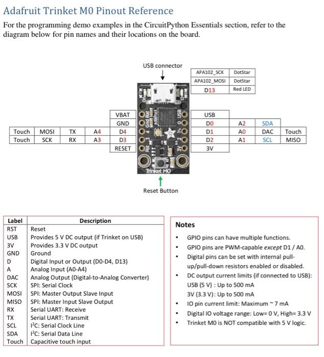
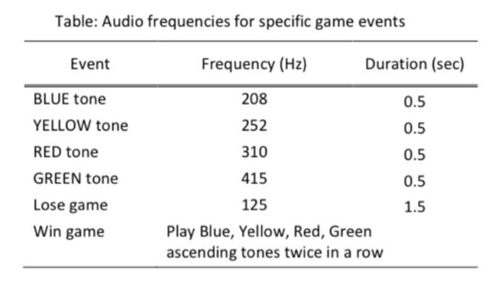
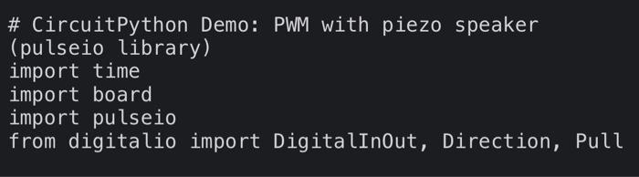
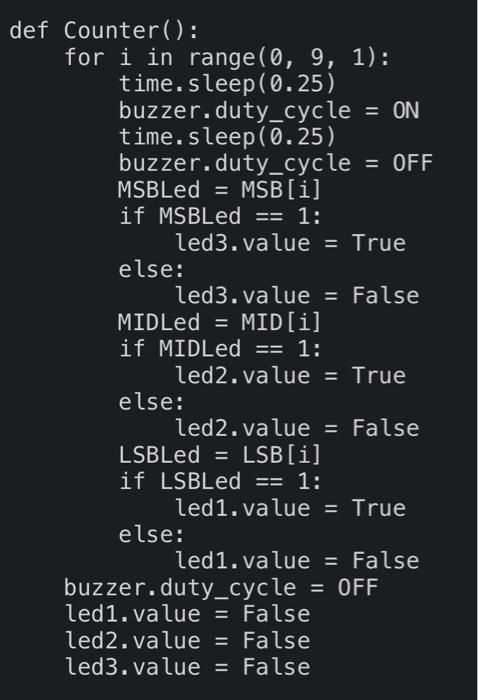
Adafruit Trinket MO Pinout Reference For the programming demo examples in the CircuitPython Essentials section, refer to the diagram below for pin names and their locations on the board. USB connector APA102_SCK DotStar APA102_MOSI DotStar D13 Red LED NOM Adat Touch Touch MOSI SCK TX RX A4 A3 VBT GND D4 , D3 RESETOK O%258 458 USB DO D1 D2 3V AZ A1 SDA DAC SCL Touch MISO OCIO Trinket MO Reset Button Label Description RST Reset USB Provides 5 V DC output (if Trinket on USB) 3V Provides 3.3 V DC output GND Ground D Digital Input or Output (DO-D4, D13) A Analog Input (AO-A4) DAC Analog Output (Digital-to-Analog Converter) SCK SPI: Serial Clock MOSI SPI: Master Output Slave Input MISO SPI: Master Input Slave Output RX Serial UART: Receive TX Serial UART: Transmit SCL 1C: Serial Clock Line SDA 1C: Serial Data Line Touch Capacitive touch input Notes GPIO pins can have multiple functions. GPIO pins are PWM-capable except D1 / A. Digital pins can be set with internal pull- up/pull-down resistors enabled or disabled. DC output current limits (if connected to USB): USB (5 V): Up to 500 mA 3V (3.3 V): Up to 500 mA 10 pin current limit: Maximum - 7 mA Digital 10 voltage range: Low=0 V, High=3.3 V Trinket MO is NOT compatible with 5 V logic. Table: Audio frequencies for specific game events Event Frequency (Hz) Duration (sec) 208 0.5 BLUE tone YELLOW tone 252 0.5 RED tone 310 0.5 GREEN tone 415 0.5 1.5 Lose game Win game 125 Play Blue, Yellow, Red, Green ascending tones twice in a row # CircuitPython Demo: PWM with piezo speaker (pulseio library) import time import board import pulseio from digitalio import DigitalInOut, Direction, Pull def Counter(): for i in range(0, 9, 1): time. sleep(0.25) buzzer.duty_cycle = ON time. sleep(0.25) buzzer.duty_cycle = OFF MSBLed = MSB[i] if MSBLed == 1: led3.value = True else: led3.value = False MIDLed = MID[i] if MIDLed == 1: led2.value = True else: led2.value = False LSBLed = LSB[i] if LSBLed == 1: led1.value = True else: led1.value = False buzzer.duty_cycle = OFF led1.value = False led2.value = False led3.value = False Adafruit Trinket MO Pinout Reference For the programming demo examples in the CircuitPython Essentials section, refer to the diagram below for pin names and their locations on the board. USB connector APA102_SCK DotStar APA102_MOSI DotStar D13 Red LED NOM Adat Touch Touch MOSI SCK TX RX A4 A3 VBT GND D4 , D3 RESETOK O%258 458 USB DO D1 D2 3V AZ A1 SDA DAC SCL Touch MISO OCIO Trinket MO Reset Button Label Description RST Reset USB Provides 5 V DC output (if Trinket on USB) 3V Provides 3.3 V DC output GND Ground D Digital Input or Output (DO-D4, D13) A Analog Input (AO-A4) DAC Analog Output (Digital-to-Analog Converter) SCK SPI: Serial Clock MOSI SPI: Master Output Slave Input MISO SPI: Master Input Slave Output RX Serial UART: Receive TX Serial UART: Transmit SCL 1C: Serial Clock Line SDA 1C: Serial Data Line Touch Capacitive touch input Notes GPIO pins can have multiple functions. GPIO pins are PWM-capable except D1 / A. Digital pins can be set with internal pull- up/pull-down resistors enabled or disabled. DC output current limits (if connected to USB): USB (5 V): Up to 500 mA 3V (3.3 V): Up to 500 mA 10 pin current limit: Maximum - 7 mA Digital 10 voltage range: Low=0 V, High=3.3 V Trinket MO is NOT compatible with 5 V logic. Table: Audio frequencies for specific game events Event Frequency (Hz) Duration (sec) 208 0.5 BLUE tone YELLOW tone 252 0.5 RED tone 310 0.5 GREEN tone 415 0.5 1.5 Lose game Win game 125 Play Blue, Yellow, Red, Green ascending tones twice in a row # CircuitPython Demo: PWM with piezo speaker (pulseio library) import time import board import pulseio from digitalio import DigitalInOut, Direction, Pull def Counter(): for i in range(0, 9, 1): time. sleep(0.25) buzzer.duty_cycle = ON time. sleep(0.25) buzzer.duty_cycle = OFF MSBLed = MSB[i] if MSBLed == 1: led3.value = True else: led3.value = False MIDLed = MID[i] if MIDLed == 1: led2.value = True else: led2.value = False LSBLed = LSB[i] if LSBLed == 1: led1.value = True else: led1.value = False buzzer.duty_cycle = OFF led1.value = False led2.value = False led3.value = False
Step by Step Solution
There are 3 Steps involved in it

Get step-by-step solutions from verified subject matter experts